(This data was captured from the Henderson site)
Summer 2000 was a big year for my 63 Stud. I met Pete Kurzenhauser
in Great Falls, VA through the SDC. I had inquired about his Ford T-5
transmission conversion. I visited him, took some pictures, and he even
let me test drive his T-5 Studebaker. I bought a new Ford MotorSport
T-5 transmission on E-bay and decided to also go to a Ford 9" rear
with disk brakes. Obviously, I don't mind straying from original, and
intend for the final product to be a resto-mod street rod. This is
Chandler and I after receiving the rear (also purchased on E-bay) from
a '77 Lincoln Mark V. I wish I had a before shot, but this is the first
time I thought of it. I torched off all brackets, and disk-sanded all
the years of rust off. The Stude rear was 58 1/2" from wheel
mounting surface to surface both front and rear. I plan on eventually
putting a Mustang II front clip on so I called Fat Man Fabrications to
ask what their width was--56 1/2". I therefore decided to make
this rear 57 1/2". A happy medium while my front is still 58
1/2" for an indefinite amount of time. The
cleaned and primed rear and axles were sent to Greg Moser Engineering
in Portland, Indiana to be shortened. I decided on 3.50 gears and got
those from Randy's Ring and Pinion in Everett, Washington. In trying to
keep the costs down, I left the rearend open-ended. New rotors,
calipers, brake lines, wheel bearings, and seals were purchased locally
at NAPA in downtown Dover.

Pete Kurzenhauser had tried to tell me about all of the Murphy-isms
he ran into during his tranny swap, but I was bound to run into my own
problems--and did. Find yourself a good machinist before you attempt
this, because you'll likely make a few trips to see him at least! The
first thing I did with the input housing was remove 1/2" length
from the end. That one I knew about. However, my biggest problem was
that my input shaft housing had a boss which interfered with the clutch
fork. Since I was using the Studebaker style pressure plate, throwout
bearing, and bellhousing, I needed to make the fork work as is. I
started taking some measurements and decided that I would slice
material off both sides of the housing boss at the same angle as the
forks when full aft. The only problem was that I expected the slices to
penetrate the housing. I removed the rubber seal from the back side of
the housing (it presses into the black area of the close-up). Luckily,
the penetrated area was forward of the seal, as you can see. I then
bought a throwout bearing, p/n N1137 from NAPA, which was a direct
match with my original bearing even though there was no direct
cross-over. I had the machinist make an interference fit sleeve to
bring the I.D. of the bearing down to slip fit with the input shaft
housing O.D. The 10.5" clutch disk was p/n 049040-150 from Jeg's
for a Mustang, and the pressure plate was a Borg and Beck (Jeg's p/n
049030-012 with centrifugal assist, or 049050-105, the non centrifugal
assist version) which was also a direct replacement item for original,
even though neither Hays nor Jegs tracked it.

Obviously, there are some steps to complete prior to this. Pete had
recommended taking runouts of the radius of the large hole and of the
aft face of the bell housing, both with respect to the flywheel. I
attempted to do this by having the flywheel surfaced and then attaching
my dial indicator with a magnetic base to the flywheel. The problem was
that when I'd rotate the engine, I couldn't get a full 360 degrees due
to the clutch release shaft behind the hole. I tried to explain this to
the machinist and gave him my questionable runouts. He simply placed
the housing on a true surface face down and took a runout of the aft
face. He found it to be parallel to the front and that was good enough
for government work--even though it had nothing to do with its trueness
in relation to the flywheel. In Pete's defense, the Studebaker manual
does say that this face must not exceed a 0.006" runout. He also
simply located the center of the large hole and opened it up from this
reference point to allow a slip fit of the T-5's bigger input housing
flange. At the same time I had this done, I had the machinist bore some
holes through the bell housing that were axially in line with the top
two holes of the transmission. The bottom two holes of the transmission
are able to use the existing bottom two holes of the bell housing. I
then bought some bolts that would extend from the inside of the bell
housing all the way to the tranny and allow room for a washer and nut.
I bought a couple of extra nuts large enough to slide over the bolt's
shank, and ground them at an angle in an attempt to match the curvature
of the inside of the bell. I then took it to someone that could use
nickel rods to weld cast iron. You can also see how the input housing
and
the clutch fork interface.
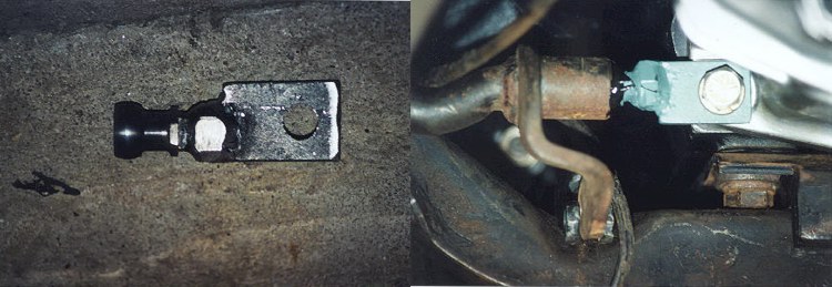
Now this idea, I borrowed directly from Pete--I just implemented it
differently. We both used a piece of 1/4" steel stock for the flat
portion, but he machined a round, barrel shaped piece for the pivot. I
removed the original pivot ball from its bracket, threaded the nut up
flush with the bottom of stud and then had the whole thing welded to
the 1/4" stock for strength. I allowed approximately 3/16"
space for movement in the ball and socket. The clutch linkage pivot
then simply bolts to the lower left transmission to bell housing
attachment point. One last thing that I had machined (that I can
remember) was an interference fit bushing on the end of the pilot shaft
to slip into the bushing in the center of the flywheel.
(UPDATE: During the summer of 2001 (while moving to Oklahoma)
I discovered that the clutch disk was interfering with the flywheel.
I removed the whole assembly and took flywheel, pressure plate
and disk to Springfield Clutch and Driveline Rebuilders in Springfield,
Missouri. While there, we discovered that a Mustang input shaft
bearing could be separated into two parts: the internal roller
bearing which was interference fit with an outer spacer. It just
so happens that the roller has a perfect interference fit with the I.D.
of the Stude flywheel. Therefore, I removed the old Stude bushing
in the flywheel and the interference fit bushing from the pilot shaft
and replaced them with a nice roller bearing in the flywheel.
They machined the interfering part of the flywheel and adjusted
the whole assembly.)
As Pete said in his report, the shifter sits a couple inches back
and to the right of its original position. I got a used Mustang shifter
(from E-bay, of course) and heated it up and straightened it. I then
had it chromed and put a Hurst classic white shift knob on it. Its
location now is better than it was originally, and the shift feel is
definitely more positive. Lastly, I got 3 Ford drive shafts from the
salvage yard. One with the proper Mustang yoke, the second with the
proper shaft length, and the third with the proper big Ford rearend
bolted flange. C&W Autoparts in Dover, DE had the proper U-joint
which was slightly bigger and wider on one axis (for the big rearend),
and smaller and narrower on the other axis to match the
driveshaft.
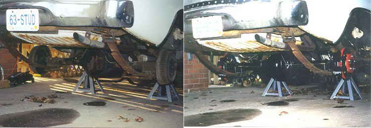
Here's the before and after of the rearend swap. AutoZone had the
direct replacement Gabriel shocks to complete the job. The whole setup
runs smooth and feels great. The car purrs along nicely at 80 MPH &
2100 RPM. It's also the only car I know of that has drum front brakes
and disk rears (for now). By the way, amazingly enough I didn't need a
proportioning valve for the brakes. They work perfectly! I can already
see myself spending the $ for a new set of leaf springs too!
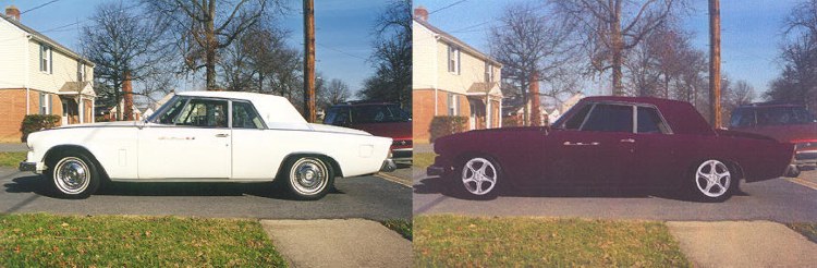
A doctored up picture along the lines of what the final product
would be like. Not necessarily the color--but it did freak my dad out.
He had the car for around 20 years before he passed it on to me in
August 1998.