
Bob's Studebaker Resource Website
Or, just to make matters truly confusing, maybe not. You see, there are several approaches to making a 2-speed motor. The two windings could be used selectively (one is fast, the other slow), or they could add positively (slow is one winding, switch in the second as well for fast), or they could add negatively (fast is one winding, switch in the other for slow). It all depends upon how the motor is constructed.
But for interval wipers, I think all you want to do is to give a short kick of power to whichever of the red or yellow wires causes the motor to run fastest when powered up on its own. I'm 99% certain you'd use the yellow wire, since it seems to be the one that gets power through the park switch when it is in the parking cycle.
You could get a clip lead, connect it to +12 volts, and simply try applying it to either the red or yellow wire at the 4-conductor plug next to the motor, and see which gives you the fastest sweep. Then use that wire to connect to your interval wiper switch.
Pseudo wiring diagram for a 1963 Studebaker Lark wiper motor and switch. I mounted it sideways under the dash of a '55 Studebaker truck. Note that I wired it so that it goes "Off, Low, High", which may or may not be the way it is on a 1963 Lark.
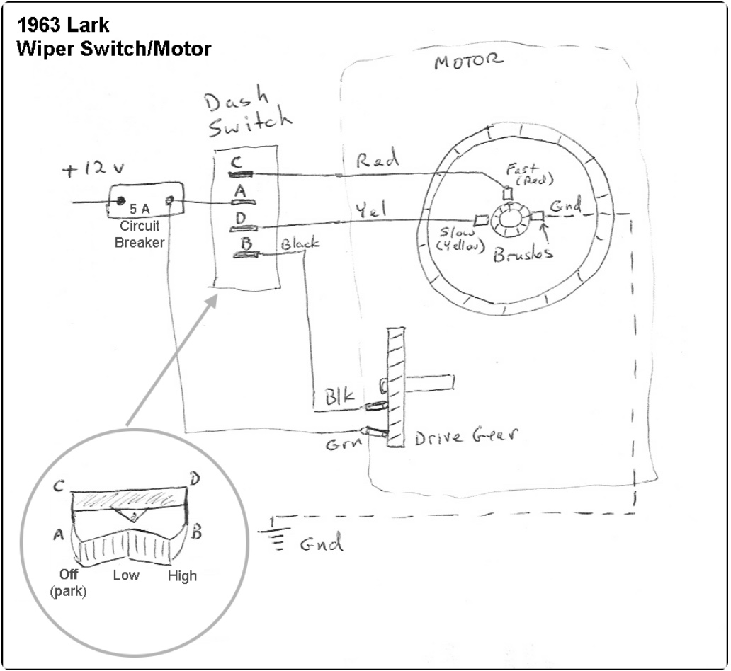
The black wire in Paul's diagram is switched power from the park cam/switch to the "slow" winding on the motor. What the diagram does not show is the connections within the switch at different settings, commonly known as a "truth table". IIRC, the switch would, in the "off" position connect B&D, and leave the others unconnected. In "slow", it would connect A&D, and leave the others unconnected. In "fast" it should connect A&C, and leave the others unconnected.
Gordr - SDC Forum