
Bob's Resource Website (2007)
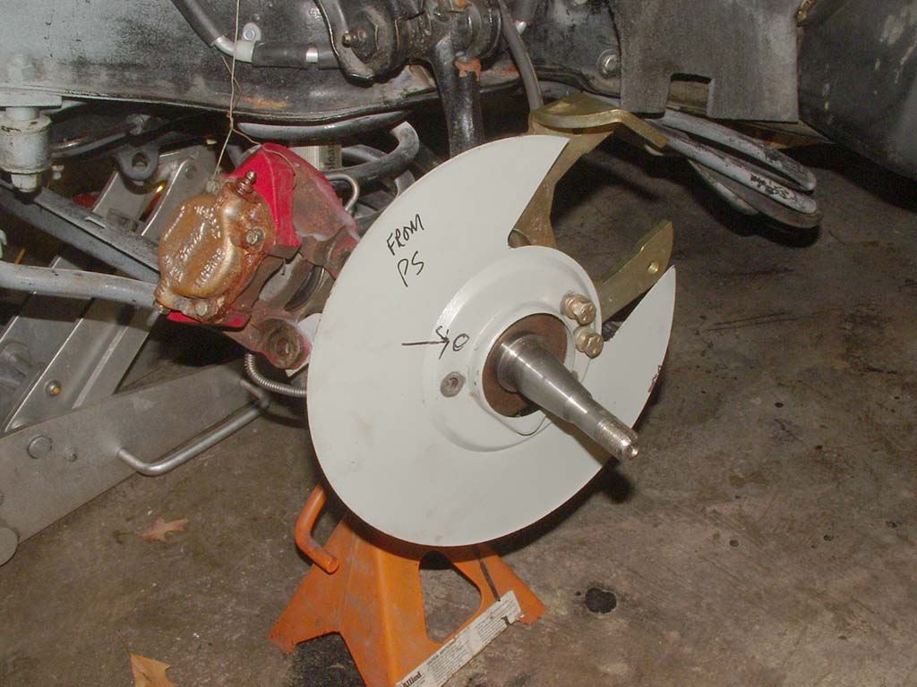
 Here's a pic of the passenger side with the stoneguards. |
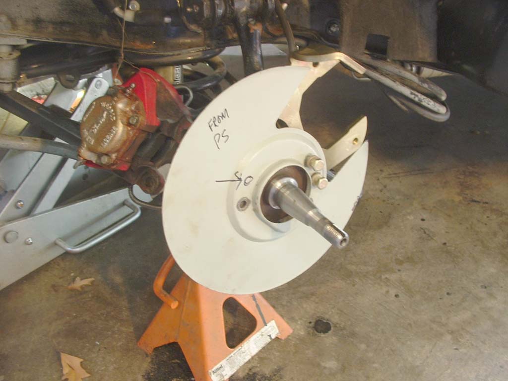
 Here's a pic of the passenger side without the stoneguards. Which would you rather have? |
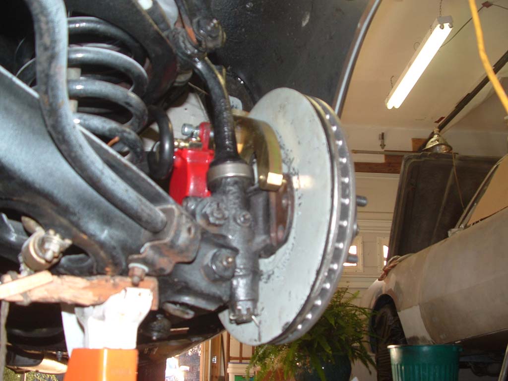 This is the drivers side.. The shields look pretty functional, eh? |
|
| REWORKING THE ROTOR GUARDS | REWORKING THE ROTOR GUARDS |
 Now we're going to take a detour from installation of the kit and remedy the above situation..The stone guards, or lack of them.
|
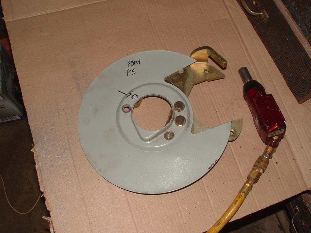
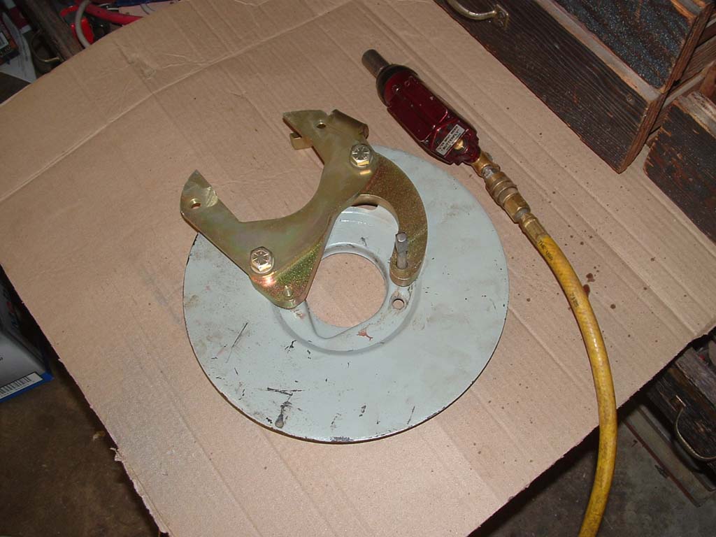
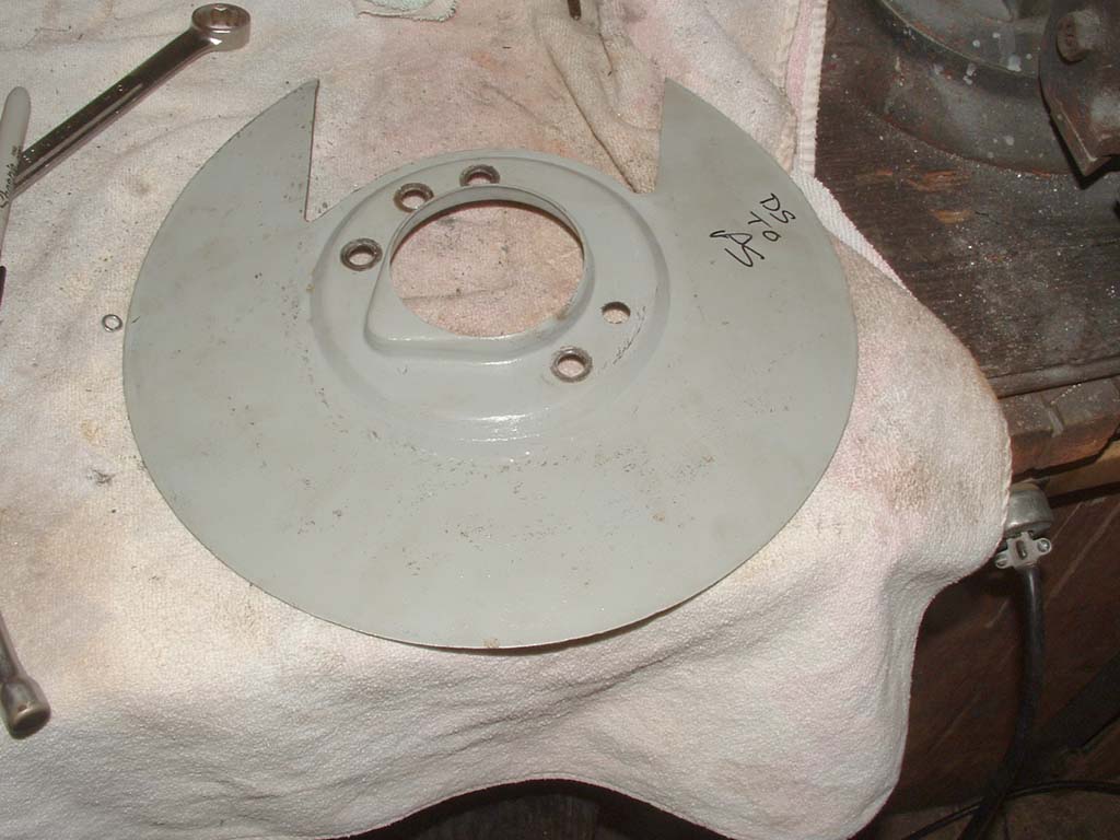
 You'll notice the drivers side guard, which we just removed had the opening for the caliper at the forward edge. If you take the passenger side guard and turn it around, and lightly fasten it to the drivers side, you'll see that it almost fits the situation right away... The spindle has three bolt holes in front and three in back. So, the three bolt holes toward the rear work fine. The one forward bolt hole is in the wrong place, so we have to drill a new hole where the upper bolt should go... |
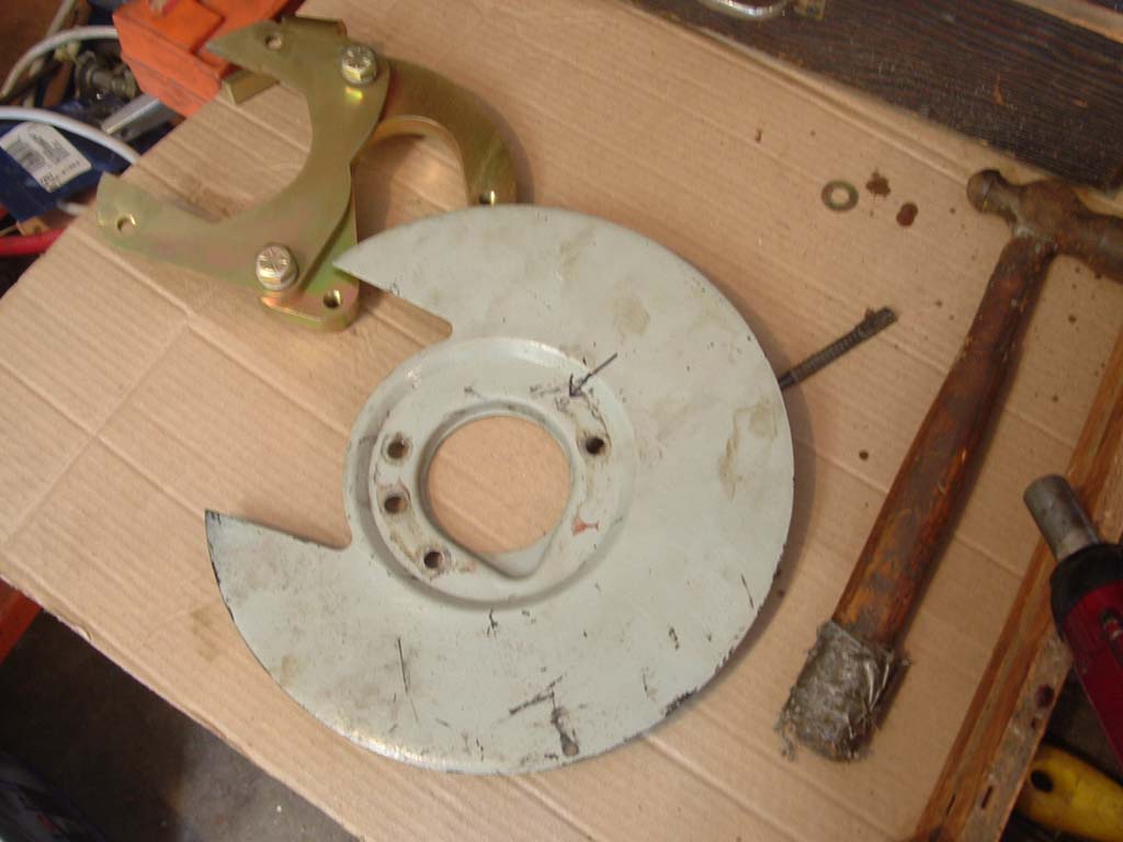
 Remove the entire bracket to a different work area, reinstall a couple of short bolts (3/8"SAE) and flip the bracket over |
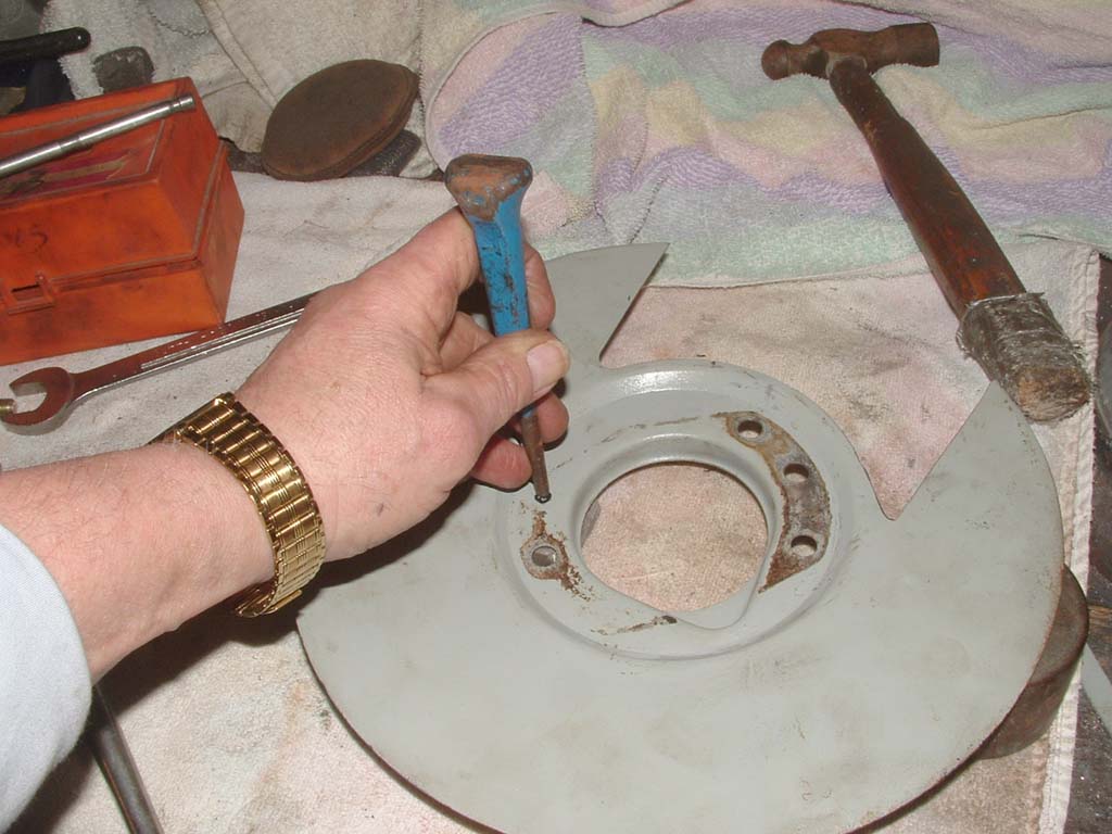
 Find a suitable punch the will fit in the 3/8" bolt hole snugly and give a couple taps with the hammer, to score the paint. |
 Removing the bracket now reveals where to drill the bolt hole. Mark it suitably. This is not a critical area, so you can be off a little, even larger than necessary. |
 Center punch and... |
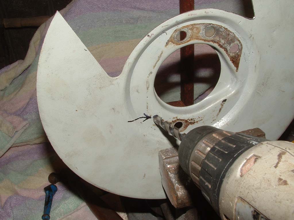 drill a 3/8" hole... |
 Filing each of the holes a bit oversize makes it easier to mount on the spindle, since you have to hold everything with one hand, while you thread the bolts with the other.. |
 Test fit on the bracket to assure the hole is suitable |
 Now, using the new bolt hole, lightly bolt it up again and see how it fits...almost. (Click on this for more detail) |
| Since I didn't take enough pics on the drivers side, AND the procedure is the same on both shields, I'm adding pics of the other side to enhance the explanation. From this point on, pics will be from each side, moving toward the finished product. |
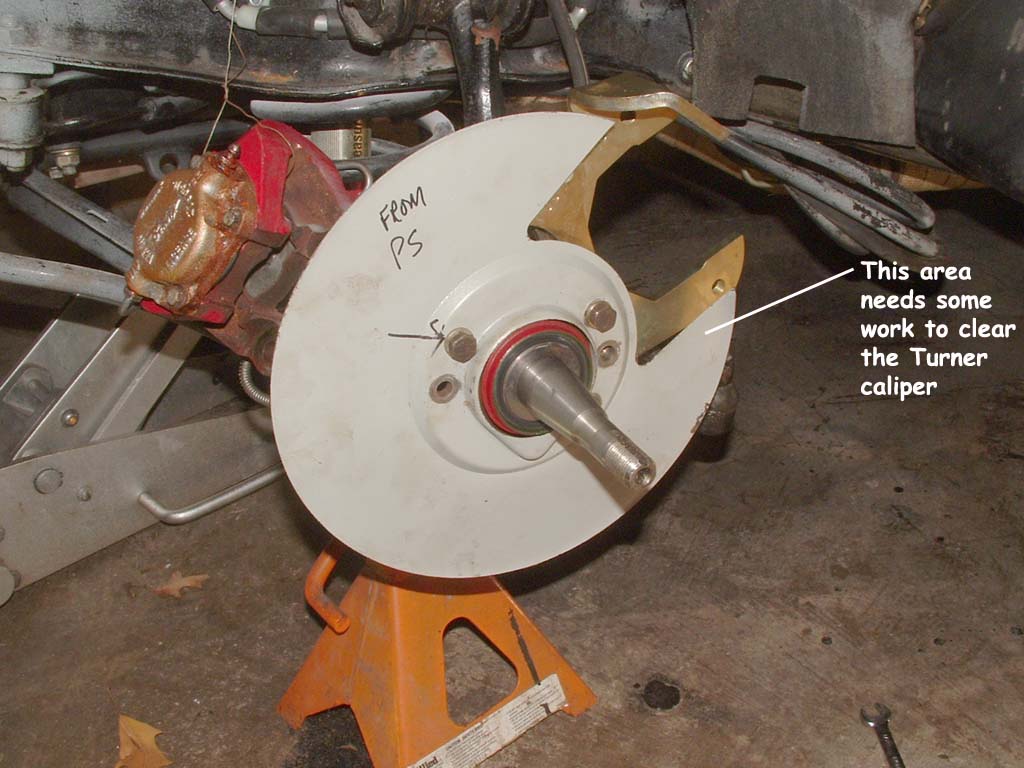
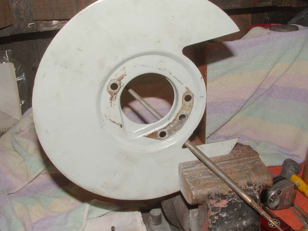
This is the part where a little work is required. The Turner caliper is wider than the old Dunlop, so the opening in the shield has to be enlarged to fit around it. |
 This section needs to be removed (Click on this pic) |
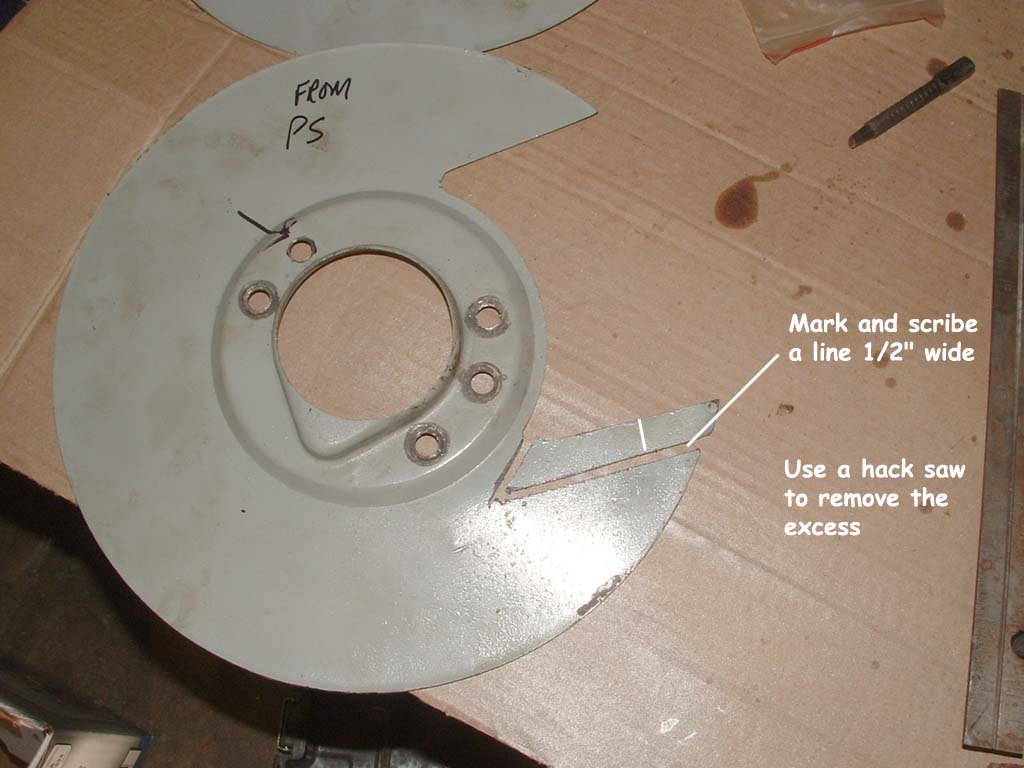
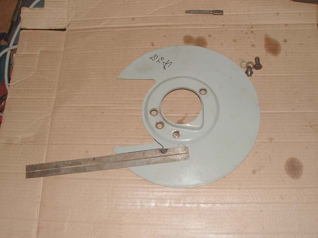 Mark a 1/2" line |
 Into the vise |
 and off |
 Clean up with a file |
 NOTE: For the New Turner Brakes (Post 2002) Remove a bit more of the corner, to accomodate the "low Pad" tab |
 |
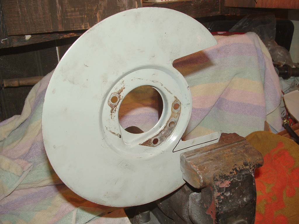
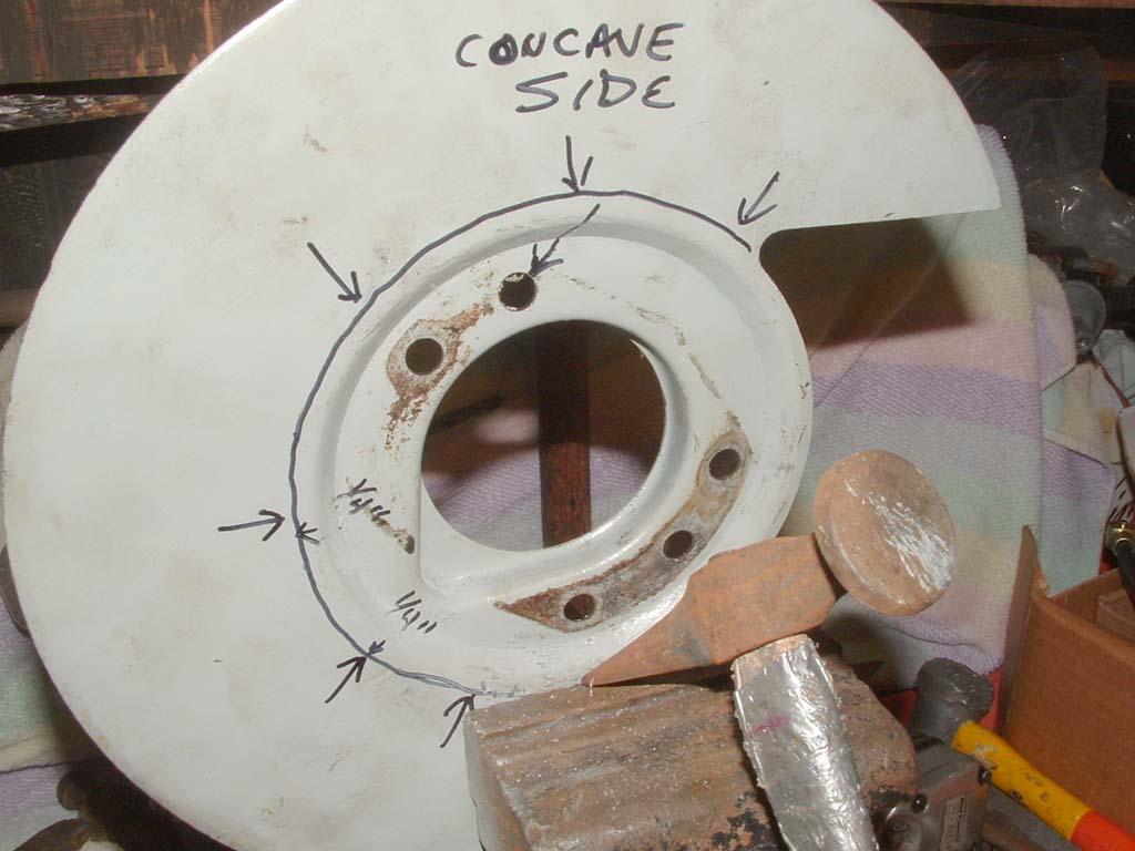
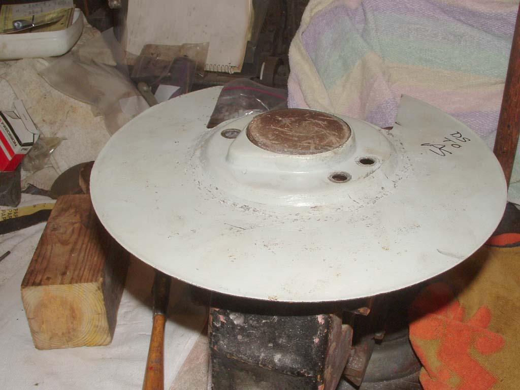
The center depression, where the bolt holes are, is set deeper than the outer area where I've marked "Concave side". The Turner rotor is much thicker than the old solid disk, so in order to have the shield clear the rotor, the mount area has to be coaxed a bit deeper. What has to be done is to make the area where the line is arced, near the same depth as the center depression. |
 Set the shield firmly in a vise... |
 Use moderate raps, with a planishing or ball peen hammer to make the shield form inward |
 Work your way around the perimeter |
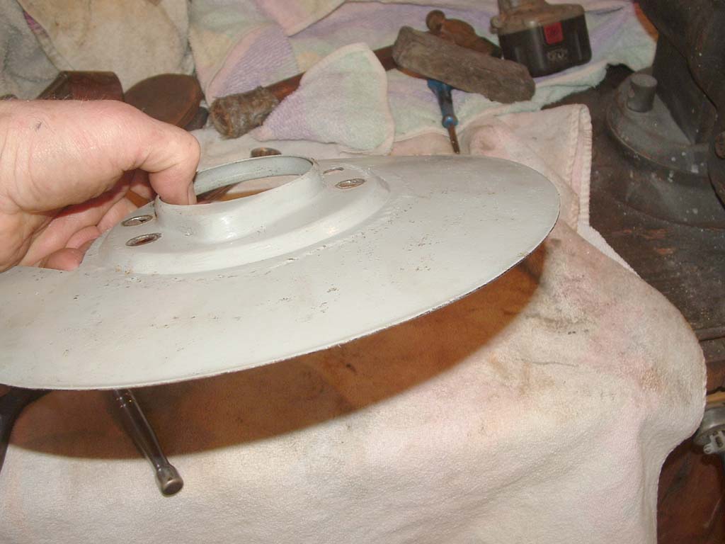
 .. you can see the convex area increasing as you work. |
 Work on this and test fit on the wheel by using the short 3/8" bolts in a couple places. Mount the rotor |
 The goal is to make the mounting area deeper, to clear the thicker Turner rotor. |
 (Click on me) There's a noticible difference now, in the depth of the mounting area. |
The shields mount on the outside of the spindle. The bracket fits behind the spindle. The bolts to mount the bracket are placed through the shield, through the spindle and into the bracket. NOTE: The bracket and bolts are made to a high degree of precision. The bolts are 3/8" SAE and fit very snugly, so it's important to avoid cross threading these. Oversizing the holes in the shield just a little bit, increases the ease with which you can thread the bolts, given you have to hold everything in one hand while inserting the bolts with the other.
If you follow this procedure, you will be doing quite a few test fits. Test fitting requires you mount the bracket, shield with lightly held bolts. You can use shorter bolts in the testing if you have them. You must install the rotor, outer bearings, washers and tighten the spindle nut to spec, to see if the rotor is binding on the shield. |
![]()
Some technical opinions are my own from experience, other informational data is from online sources with credits when available and while care has been taken to be as accurate as possible, it is offered only as a guide and caution should be exercised in the application of it.