Bob's Resource Website (2007)
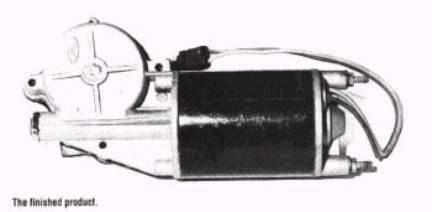
Studebaker Power Window Motor Repair
These files were created from an article by Richard Prince, of Auto Restorer magazine, October 1999. He collaborated with Bob Clayton, of Suwanee, GA, who used to repair these motors for a living.
Bob Clayton passed away in early 2004
Power windows became available on many luxury cars in the
1950’s and by the following decade, were found on many medium and even lower
priced cars, as well.
Some of the
earlier systems relied on hydraulic power to raise the windows. With those systems, an electric motor drives
a pump. With assistance from valves,
the pump delivered pressurized hydraulic fluid to rams at each window. Typically the hydraulic ram raises the
window and a relatively powerful spring, in concert with gravity, lowers it,
when the valve is opened to relieve the pressure in the ram.
By the 60’s,
however, hydraulic power windows were a thing of the past and almost all cars
relied on electric motors to raise and lower each window. Electric window motors and mechanisms are
generally quite sturdy and reliable, but like everything else, they deteriorate
over time.
The two biggest
enemies of electric power windows are corrosion and excessive heat. Corrosion
comes from moisture in the air, in some cases, immersion in water. Power windows motors are always mounted in
the doors or between outer and inner body panels. If drain holes in these areas get clogged, they can harbor
significant quantities of water.
As with any
electric motor, the amount of heat generated by a power window motor, increases
significantly, as the load, which it’s subjected to, increases. The load increases, as resistance increases
in the systems mechanicals by lack of lubrication.
Anything that
increases resistance on old mechanical components, such as old hardened gummy
grease, distorted arms, broken rollers, bent tracks and so on, makes the motor
work harder and hotter.
In addition to the
increased mechanical resistance, increased electrical resistance in the motors
circuitry also generates added heat.
Loose connections and corrosion are the most prevalent causes of higher
resistance.
If you have a
window motor that is tired or failed altogether, restoration is in order.
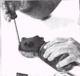
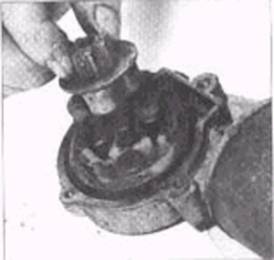
Photo 1 Photo 2
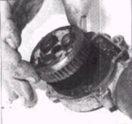
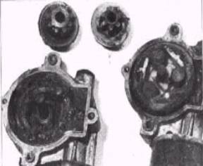
Photo 3
Photo 4
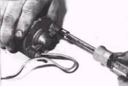
Photo 5
Begin by removing
the gearbox cover as shown in Photo #1.
The cover is held on by a single screw and may require some gentle
prying after the screw is removed.
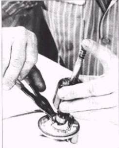
Next, remove the
driven gear (also called the second reduction gear) from the drive gear, as
shown in Photo #2. The driven gear,
which is metal, simply lifts out, but sometimes it’s stuck and will take some
effort to remove.
Lift out the drive gear, which is made of nylon, as shown in
Photo#3. There should be three
cylindrical pieces of nylon, located in the recess in the face of the drive
gear, but these are frequently broken apart and unrecognizable.
The window motor directly drives a worm gear, which is
machined into the armature. The worm
gear, in turn, drives the nylon drive gear, you just removed. The metal driven gear (second reduction
gear) that you removed earlier, sits in the recess, in the face of the drive gear
and is locked in place by the threee cylindrical pieces of nylon. In other words, the three cylindrical pieces
of nylon act as keyways for the metal driven gear.
The motor spins
the worm gear and the worm gear turns the nylon drive gear. The metal driven gear is sitting on a shaft
on the face of the nylon drive gear and the two are locked together by the
three nylon cylinders, so when the nylon gear spins, the metal gear also
spins. The metal gear actually raises
and lowers the window. Why not have
just the nylon gear raise or lower the window?
The metal gear is
a second reduction gear that reduces the rpm of the spinning motor, increasing
the torque multiplication and reducing the speed at which the window moves.
And why is the
nylon gear coupled to the metal driven gear, by the three nylon cylinders?
The cylinders act
as a shock absorber, helping to dissipate the sudden load generated when the
window reaches it’s top or bottom.
Without those
cylinders, something in the window mechanism would break or wear out relatively
quickly from the repeated impacts.
Over time, the
three cylinders get increasingly brittle and owing to the repeated loads they
must endure, they crack and then break apart.
When this happens, you hear a “clack, clack, clack” sound, when the
window is at the top or bottom and the motor is still turning.
Eventually, the
window stops moving altogether because withouot the three cylinders, the metal
driven gear is n o longer lockedto the nylon drive gear. When this happens, either the motor spins
the drive gear, but the driven gear
remains stationary or the motor jams because of the broken – up debris.
Photo #4 shows two
nearly identical motors with the gearbox covers off and the metal driven gears
removed. The three nylon cylinders in
the motor on the left have all but disintegrated into the gear box grease,
while the cylinders in the motor on the right are intact. Even if the cylinders in the motor look
good, it is advisable to replace them, since they can fail in a relatively
short time, in spite of their seemingly
good appearance.
Most motors have
alignment marks on the gearbox, motor housing and motor endplate. If yours is not marked, use a small punch to
mark it, so the parts can be reassembled in their correct orientation.
After you remove
the drive and driven gears from the gearbox,
and make certain the parts are marked for proper alignment, unscrew the
two long bolts that hold the motor and gearbox together, as shown in Phoito#5.
Next, separate the
motor end plate, brush holder from the motor’s housing as shown in Photos
#6. There should be a thin paper gasket
between the two and sometimes they are stuck.
If so, pry gently with a small screwdriver or tap lightly with a soft
face hammer.
Separate the motor
housing from the gearbox as shown in Photos #7. As with the endplate, the housing and gearbox may be stuck
together, thus requiring some gentle persuasion to take apart.
Slide the
armature out of the motor’s housing as shown in Photo #8.
If you motor is a
permanent magnet type, like the one illustrated here, it will take some effort to take the armature out. Pull it firmly to overcome the force of the
magnets that are bonded to the inside of the motor housing.
The two
brushes, which are held in place in the motor’s end plate, are normal wear
items that should be replaced, in the course of the rebuild. One is ‘soldered’on and can be ‘unsoldered’
with a soldering iron, as shown in Photo #9.
the other brush is welded on and can be clipped with wire cutters. Set the brushes aside or later reference.
As you will have
noticed by now, the inside of the motor and gearbox, are quite messy. The inside of the gearbox was packed with grease when new and by now,
some or all, has become solidified.
In addition, as
pointed out earlier, you will likely find broken plastic debris mixed into the
caked-up grease. The inside of the
motor has to be full of black carbon dust, created as the brushes wore. It is also likely that you’ll find rust here
and there and a general coating of muck.
To clean up the
window motor parts, use a parts washer or soak them in a cleaning solvent for a while . After the parts are clean, dry them and
blow them off with compressed air.
Use a glass bead
cabinet to lightly blast the motor housing, endplate and gearbox. This cleans off any corrosion, solidified
grease and other blemishes. (EOP2)
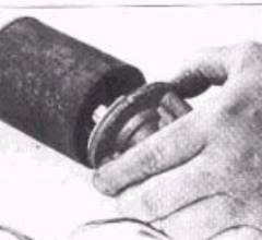
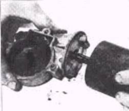
Photo 6 Photo 7
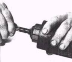
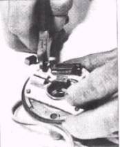
Photo 8 Photo 9
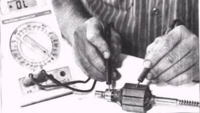
Photo 10
CHECK THE WINDINGS
If you have a
wound motor and have a break in the winding, the motor will not work. Use a continuity tester to evaluate the
continuity of the winding. If there is
a break, you will need to replace the armature with a good one or have the bad
one rewound.
It is also
possible for the winding to have continuity and still be bad. The wire that forms the winding must be
insulated and if the insulation breaks down, there will be continuity, but
little or no magnetism. The wire is
insulated with an electrical insulating varnish that deteriorates with
excessive, prolonged heat. If this
happens, the armature must be replaced, rewound or reinsulated.
While rewinding
the armature with brand new wire, is certainly an effective route to take, it
can be difficult to find someone capable and willing to perform this
service. To avoid having to rewind armatures, there is a very effective means to re-insulate the wiring.
Begin by
thoroughly cleaning the armature with brake cleaner to remove any grease, oil
or contaminants that will inhibit adhesion.
Then thoroughly dry off with compressed air. Bake the armature at 300 degrees F. for approximately 10 minutes
to remove any moisture and get the winding hot.
While the
armature is baking, place enough electrical varnish in a pot, so you can
totally submerge the winding and heat the varnish on the stove with the burner
set at it’s lowest position.
Dip the (still
hot) winding into the container of hot electrical varnish and let it soak for
30 minutes. Remove the winding from the
varnish, place it on aluminum foil and bake it in the oven for 30 minutes at
300 degrees F.
Remove the armature
from the over after 30 minutes and let it cool. Once cool, remove the varnish from the commutator and armature
shaft with lacquer thinner or a similar solvent.
In addition to
testing the armature windings for continuity, you should also test to make sure
the armature winding core doe NOT have continuity to the commutator as shown in
Photos # 10.
Finally, test each
of the commutator bars for continuity to one another as shown in Photo #11. The
commutator bars, like the windings, need TO BE continuous.
The ends of the
armature shafts must spin freely in their bushings, so it’s important they’re
clean. Briefly, wire wheel the shaft
ends, as shown in Photo #12, to remove any glaze or other foreign material.
In order to clean
and true the commutator surface, use a lathe, as shown in Photo #13 or mount
the armature in the chuck of a variable speed drill, clamped or mounted in a vise.
Use a fine file to dress the surface of the commutator and then
compressed air to remove the filings from the armature.
With all the parts cleaned and dry, the armature tested and
the commutator lightly resurfaced, you are ready to begin reassembly. (EOP3)
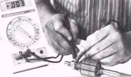
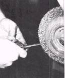
Photo 11 Photo 12
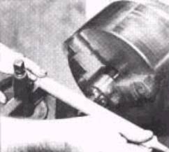
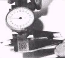
Photo 13 Photo 14
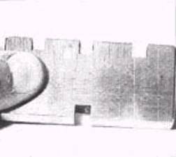
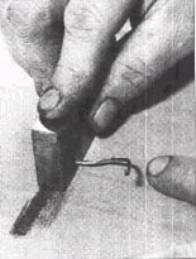
Photo 15 Photo 16
BRUSH PREPARATION
As stated
earlier, brushes normally wear out and should be replaced with new ones. Purchase brushes slightly larger than
required and cut them down top a precise fit.
As shown in Photo #14, use a micrometer to measure the dimensions of the
original brushes to use as a guide in fitting the new ones.
The brush holders
in some motors are plastic. When the
motors were new, the brushes were slightly oversized and the plastic expanded
to accommodate them. By now the plastic
is brittle, so make replacement brushes, just the right size to avoid cracking
the plastic.
At the same time,
however, it is important to NOT make the brushes undersized. If they are not snug in the holders, they
can become cocked and contact the commutator at an angle. The misalignment will provide less than 100
percent contact until the brushes wear down at the angle.
In order to cut the
brushes down, use a tool as shown in Photo #15
The different
sized grooves hold the brush securely, while it is passed over fine sandpaper,
on a flat surface, as shown in Photo #16.
Always purchase
high quality replacement brushes for
your motor.
Original brushes
were predominantly carbon, with little or no copper. New brushes have 70 percent copper content, which allows then to
conduct much more efficiently. Better conductivity means lower amperage draw,
which indicated the need for that large relay, fitted to the original motor
circuit.
In addition to
cutting down the brushes so they fit their holders properly, you also need to
cut down the ends. When doing so, your
objective is to leave them as long as possible, so as to prolong their lives,
without permitting them to bind against the commutator. Fitting the end dimensions is usually a
trial and error process that requires installation and removal of the brushes
several times. (EOP4)
 REASSEMBLY
Photo 17
Installing the brushes is somewhat of a tricky
undertaking. Both are held firmly
against the commutator by small springs that are inserted into the brush holder
before the brush goes in. You must
insert the spring, then the brush and then push and hold the brush against the
spring tension. While holding each side
in, you insert the commutator end of the armature into the bushing in the end
plate, so the commutator is between the brushes, Photo #17
This is an operation that would go easier if we had three
hands. You can make a tool to
facilitate this process by using an old pair of snap ring pliers, Photo #18
Once the brushes are
correctly sized, you should lap then to the commutator. To do this, install the brushes in their respective
holders and insert the commutator into the endplate. Be sure to put a dab of grease onto the armature shaft end.
(Photo #19) Synthetic disk brake
caliper grease is recommended, in that it’s resistant to heat.
With one end of the armature shaft inserted into it’s
bushing in the motor end plate, chuck the other end of the shaft into an
electric drill. Then, as shown in Photo
#20, spin the armature while holding a commutator stone against the commutator. A commutator stone contains abrasives similar
to valve lapping compound. The spinning
commutator picks up the material and accelerates the wear on the end of the
brush. After a minute or so, the
brushes are worn, so that they conform to the surface of the commutator.
When you’re finished lapping the new brushes, take them out
and clean the commutator stone dust off everything. Electrical contact cleaner, such as the Gunk brand aerosol spray
( Photo #21) works well for this task.
After everything
is cleaned up, you should dress the contact points.
To prevent a
meltdown from excessive heat, , the motor utilizes a simple, but effective
electrical interruption system. The
circuit from one of the brushes goes through a set of contact points. One of the points is held by what is called
a bimetal laminate arm. This is a small
arm formed from 2 strips of metal, each having a different rate of thermal
expansion. If the motor gets very hot,
the bimetal arm also gets hot. Because
one metal strip expands more than the other, the arm curls and in the process,
separates the two contact points. This
opens the circuit and prevents the motor from continuing to operate.
As with the contact
points in your car, the mating surfaces of the motor’s points can become
corroded and irregular. To fix this,
fold a small piece of #600 grit or finer sand paper, so the abrasive material
is on both sides. Spray the paper with
a little electrical contact cleaner to act as a lubricant and insert the paper
between the two points. Move the paper
back and forth several times to clean up the point surfaces (Photo #22)
Just as you did
after lapping the brushes, use electrical contact cleaner to clean the points
and surrounding area of any sanding dust or other impurities.
SOLDERING IN PLACE
The next step is to
solder the wire leads coming out of the new brushes to their respective
spots. As shown in Photo #23, use a
miniature wire wheel in a rotary tool to clean up the areas where the wire leads need to be soldered, in order
to promote adhesion. Give the area a
good blast of compressed air or electrical contact cleaner after wire wheeling
to assure there is no errant debris.
New brushes come
with rather long leads that you usually have to cut down slightly. The goal is
to make the leads long enough to accommodate the travel of the brushes as they
wear, but not long enough to get in the way or come in contact with anything
else. Sizing the leads correctly is
particularly important with wire wound motors because with this type of motor,
the long bolts holding the motor housing, end plate and gearbox together, are
quite close to the leads. If one of the
bolts touches one of the brush leads, it will create a short circuit.
After you have
trimmed the leads to their proper length, you need to solder them in place, as
shown in Photo #24. It is important to
use silver solder, rather than regular tin based solder because the silver has
a higher melting point. Remember to use
silver solder flux with the silver solder.
(EOP5)
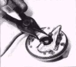
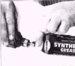
Photo 18
Photo
19
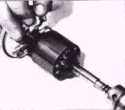
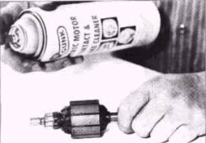
Photo 20 Photo 21
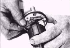
Photo 22
You are now ready
to install the brushes and armature into the end plate for the final time.
Don’t forget to again lubricate the armature end of the shaft with some high
temperature grease.
INSTALL THE ARMATURE
The next step is to unite the end plate / armature assembly
with the motor housing. This is tricky
with a permanent magnet motor because the magnets bonded to the inside of the
motor housing can quickly yank the armature out of the end plate, when you
start to insert the armature into the housing
Make sure the
alignment marks are lined up when you the housing into the end plate and don’t
forget the gasket that goes between the two.
Also remember that the magnets are not longitudinally
centered in the housing (They are closer to one end than the other, as shown in
Photo # 25)
When assembled, the magnets are closer to the end plate than
to the gear box. This allows the armature
windings to be fully encased by the magnets for maximum efficiency.
The best way to put
the housing and end plate armature assembly together tis to constantly push the
armature and end plate while manipulating the housing.
Hold the
armature/end plate in one hand, squeezing the two together. As you start to insert the armature in the
housing, put your other hand into the as far into the housing as possible until
you reach the armature shaft coming in from the other side.
Use one hand to push the end plate onto the armature and the
other hand to push the armature onto the end plate, while using fingers from
both hands to slide the motor housing down over the armature as shown in Photo
#26.
When the armature
end plate assembly is fully inserted into the housing, it will tend to stay in
place until you bolt it all together.
As shown in Photo #27, put a light coating of high temperature grease on
the portion of the armature shaft that rides in the gearbox and on the shafts
end.
Install a new gasket
on the gearbox housing as shown in Photo # 28 and slip the housing over the
armature shaft. Make sure the
alignment marks line up and then install the two long bolts through the end
plate to hold it all together.
Some power window
motors utilize an o-ring in a groove on the armature shaft to keep grease in
the gearbox from entering the motor. If
your motor has one, you should replace it at this time.
There is an adjustment screw in the gearbox housing that is
used to adjust the endplay of the armature shaft. If you have not changed the end plate, motor housing, gearbox or
armature, then you should not have to make any adjustment.
If any of these parts have been changed or the adjustment
was bad to begin with, then you should adjust the shaft position. Loosen the adjustment screw locknut, turn
the adjustment screw in until it contacts the armature end as shown in Photo
#29. Then, turn it out ever so slightly
that there is no discernible endplay, but at the same time, the shaft is not
binding or dragging on the screw. Tighten the adjustment screw locknut to hold
the screw in position.
Use a liberal
amount of grease to coat the inside of the gearbox, as shown in Photo #30. White grease is preferred because of it’s
tendency to have less drag on parts.
NEW SHOCK ABSORBERS
If the three
cylindrical nylon shock absorbers, described earlier are broken, they must be
replaced. But even if they look ok,
it’s a good idea to replace them anyway, since their failure is almost a
certainty. (EOP6)
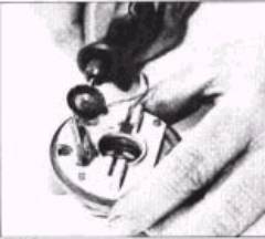
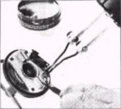
Photo 23 Photo 24
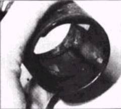
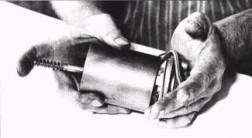
Photo 25 Photo 26
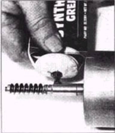
Photo 27
You
can buy replacement shock absorbers from a number of sources, but as shown in
Photo #31, he cuts three new absorbers from his own stock. The next step is to
liberally lubricate the inside of the
nylon drive gear with white grease.
Then, insert two of the cylinders into the nylon drive gear, place the
metal driven gear part of the way in, and simultaneously wedges the third
absorber in while pressing the metal gear into place. As shown in Photo #32, it is helpful to use a small screwdriver
to help force the third shock absorber into place.
After the two reduction
gears and three cylindrical shock absorbers are put together, place the entire
assembly into the gearbox as shown in Photo # 33.
Pack some more
grease into the gearbox, so everything there is well coated. Then, as shown in Photo #34, reinstall the
gearbox cover. Before reinstalling the
motor in the vehicle, it is advisable to bench test it. Use a car battery to make sure the motor
spins freely in both directions, as shown in Photo #35.
Also, listen for
any unusual sounds as the motor spins, as that would indicate a problem. If it sounds like the motor is straining,
try loosening the armature shaft adjustment screw slightly. Turn the screw in or out listening to the
motor. The screw places the armature in
the center of the windings, which is where they should be.
After everything
checks out, the final step is to refinish the exterior of the motor. Usually the motor’s housing was painted
semi-gloss black, while the end plates were left natural. In some instances, the end plate was silver
cadmium plated. Some people like to
paint everything to prevent corrosion and figure that since you can’t see it
after its installed, the deviation from the ordinary doesn’t matter. Others prefer to duplicate the original
configuration of their motor and paint only that what originally painted. Regardless of how you decide to refinish
your exterior, the rebuild should last a good while.
INSPECT THE ENTIRE SYSTEM
When restoring a power window motor, don’t forget to inspect
the remainder of the entire power window system. Motor failure is often the end result of a problem that lies
elsewhere. Take a careful look at the
wiring that feeds power to the switches and motors in your car. Replace any corroded, frayed or otherwise
damaged wiring. Repair any loose
connections, bad relays or sloppy switches.
If you have a bad switch and can’t find a replacement don’t
despair. Bob Clayton can restore most
automotive switches and he does it at a reasonable price.
In addition
to inspecting the electrical components in the power window system, you should
also evaluate the mechanical components.
Petrified grease in the window tracks or regulator assembly dramatically
increases (EOP4)
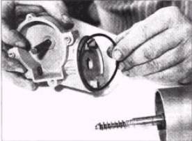
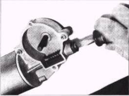
Photo 28 Photo 29
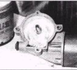
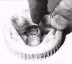
Photo 30 Photo 31
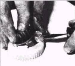
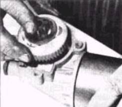
Photo 32 Photo 33
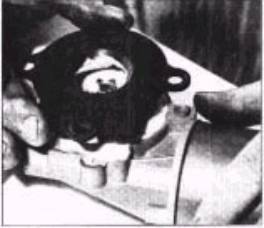
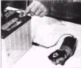
Photo 34 Photo 35
the load on the motor and will accelerate its failure. Also, look for distortions, breaks or other
abnormalities in the various parts that compose the window support and movement assemblies. Like hardened grease, these will require the
motor to work much harder than it should and
ultimately lead to failure.
SOURCE
Bob Clayton
611 Eva Kennedy Road
Suwanee, GA