|
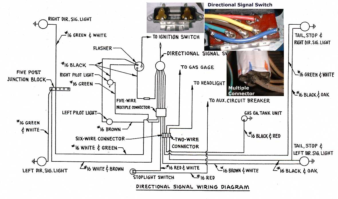
How do the turn signals work? From alt.autos.studebaker Robert Kabchef: David, Surely you're aware that the T/S switch serves to isolate the rear bulb's stop filament from the brake light circuit and use it as the blinker, no? In other words, when the turn signal switch is centered, the brake light switch sends power to it and through it's contacts (the T/S switch) to the two brake light filaments. These early 50s cars, the T/S system was still an option. but looking at the parts book shows the same taillight harness for all 53s. That would make me think that you need to reconfigure the wire arrangement under the dash to accommodate your T/S switch. On my '51, it seems I recall that there WAS a second bulb incorporated to give the turn signal function. Right now I'd be hard pressed to dig out the tail light bodies to confirm that for you. Paul Villforth: Mr. Dave, The stop and turn signal uses the same filament. Replacement harnesses from Studebaker used plastic coated insulation. I got one for my 51 back in 1970 and it was plastic insulation and was a Stude original. So your 53 would be original with the correct color coding. I have a drawing on how to hook up the dash indicators and it is just the opposite of the way you think it should be. If you look it up the logical way it will not work correctly. If you go to a NAPA store ask for 720524 bullet terminals. They are exactly the same as the ones Studebaker used. Hopman Jeffrey: Forgot to mention in the previous note that I did have a lot of trouble with the flasher. My car now has a "late model" fuel injection engine in it that I am working to get hooked up. So, all the accessories are going to be 12v. I got a electronic flasher to use and had a problem getting it to work. Near as I can figure, the original flasher setup had it so the blinker lamps on the dash were "grounded" through the front turn signal filaments. I think what was supposed to happen was the dash blinkers would come on when the outside ones were off and vice-versa. That way if a bulb was out on the front signals, the dash one would not come on and you would have a bulb out warning of sorts. The way my electronic flasher was setup I did not get that to work so they now come on and off at the same time as the fronts. I had to rewire the flasher socket too and the pin out was different and it would not work the first attempt. This had nothing to do with the signal switch itself. The Five Wire Multiple Connector
Pin Out
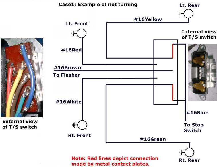
The top center photo show what's inside the switch. It contains two triangular brass plates mounted to a prestolie base. This base is free to slide on a spring incased rail. The spring holds the two triangular pads apart and in the neutral position. When you signal a turn, one of the pads will move toward the center of the assembly, creating a different circuit combination. The photo to the right, shows the assembled unit with the new wires attached. From the assembled unit I buzzed out the following connections below. The following table does not show the break light logic, just the turn signal logic:
So how does the turn
signal work? Case1: Day driving, not turning and you hit the breaks?
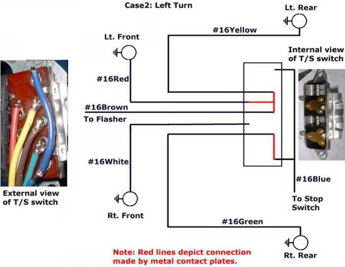
Case2: Day driving and turning left? Case3: Night driving, not turning? Case4: Night driving and turning left? Case5: Night driving and turning left at a stoplight? Why do the dash turn indicators
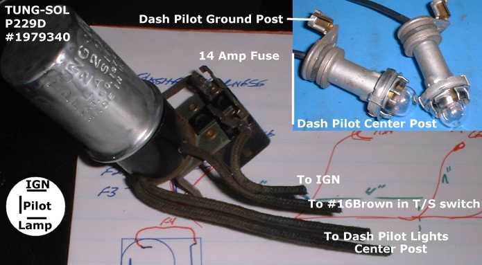
have two wires feeding them? LGeoCole: The dash lamps get power from the flasher. That's the high side. The low side is the front turn signal lamp that's not being used. The T/S lamp takes a lot more current to light than the dash lamp so most of the voltage shows up across the dash lamp. The dash lamp glows, but the not-turning-side T/S lamp doesn't. If it weren't hooked up this way, you could only have a single dash lamp unless the switch were more complicated. Sound OK? The idea from "Hopman Jeffery" idea makes sense. If a front lamp is out, the dash light for the other side won't work causing you to look for a problem, maybe. Greg Hodge: I have been lurking this NG for about 14 months...
Most enjoyable (mostly). Time for a "Pay Back". Albeit
a Long one. An 1157 is a 12V dual filament lamp. One filament draws about .6 Amp (low power Park / Tail filament) and the other about 2 Amps (high power Brake / Turn filament). Let's say a dash indicator lamp draws .25 Amp. (all @ 12 Volts). Tail (and Park lights as they used to be known as in my youth) are a completely separate circuit from the Brake / Turn lights. Off, they're off. On, the lower power filaments are lit. Step on the brake (nothing else is on) and the brake light switch supplies power to the rear high power filaments. (Brake lights on.) Now for the complications... Add a turn signal switch and a flasher. Flasher: I have not investigated a 3 terminal flasher, but that won't stop me... A 2 pin flasher starts as a "closed" switch; power in one terminal goes through to the other. But, the power also goes through a "heater" (a serial circuit) that heats up a bi-metal strip that gets hot, bends and "opens" the switch. No current through the heater when the "switch" is open, the heater cools, the bi-metal cools and closes the "switch". This switch is the click - click of the flasher. Electronic flashers use a simple electronic circuit and relay to "click". The relay carries the current to the lamps. The electronic component(s) *mostly* determine the click timing, that's why electronic flashers work with or without the extra load of trailer lights where *some* flashers don't work so well. Turn Signal Switch: This switch switches
the 4 high power filaments at the 4 corners. It does this by
switching (all separately) the Rear (high power filaments) to
either the flasher or brake light switch; and the Front (high
power filaments) to either the flasher or an *open* circuit. Left Turn: Right Rear high power filament is still connected to the brake light switch. (Right Rear brake light operates normally via the brake light switch.) Right Front high power filament is not connected to power (no change). Left Rear high power filament is connected to the flasher (flasher blinks lamp). Left Front high power filament is also connected to the flasher (ditto). Right Turn: Uhmmm... "Mirror Image" of above. >>Also why are there two wires going to the dash pilot
lights in the factory diagram?<< Huh... What??? OK, you put a lamp that takes .25 Amp to light up IN SERIES with a lamp that takes 2 Amps to light... The lower power lamp limits the current in the circuit to say .25 Amp. The smaller lamp lights, the high power lamp filament might get warm, but Not Hot Enough to Light Up. Remember, the Right Front (high power) filament is not connected to power. And... The Right indicator also has the flashing power applied??? Correct, BUT the *other* (ground) wire for the Right indicator goes to the LEFT Front (high power) filament which also is connected to the Flasher Power. Both terminals of the Right indicator lamp are at the same (flashing) voltage at the same time. Both terminals are either *Hot* or *Cold* at the same time. No *instantaneous* voltage ACROSS the terminals... No Light. Questions anybody? Greg So how do you bench test the
flasher circuit? Greg Hodge:> I assume I should ground out the offset
connector on the pilot lights right? > Do I have to connect the flasher pulse out line to the
T/S indicator? Where can I get replacement flasher
units, I toasted mine in this exercise? |