
Bob's Resource Website (2007)
Turner Brake Install - 1964 GT Hawk
(Click images for more detail)
Note: This pictoral is displayed to show the process of installing the Turner Disk brake kit on a 64 GT Hawk, which had factory Disk brakes. The same basic steps are used to replace drum brakes.
The page targets the owner who has never done this type of modification or any heavy mechanical work, for that matter.
There may be some over simplifications , but it's meant to emphasize the means of getting the procedure accomplished.
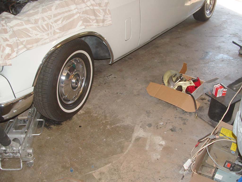
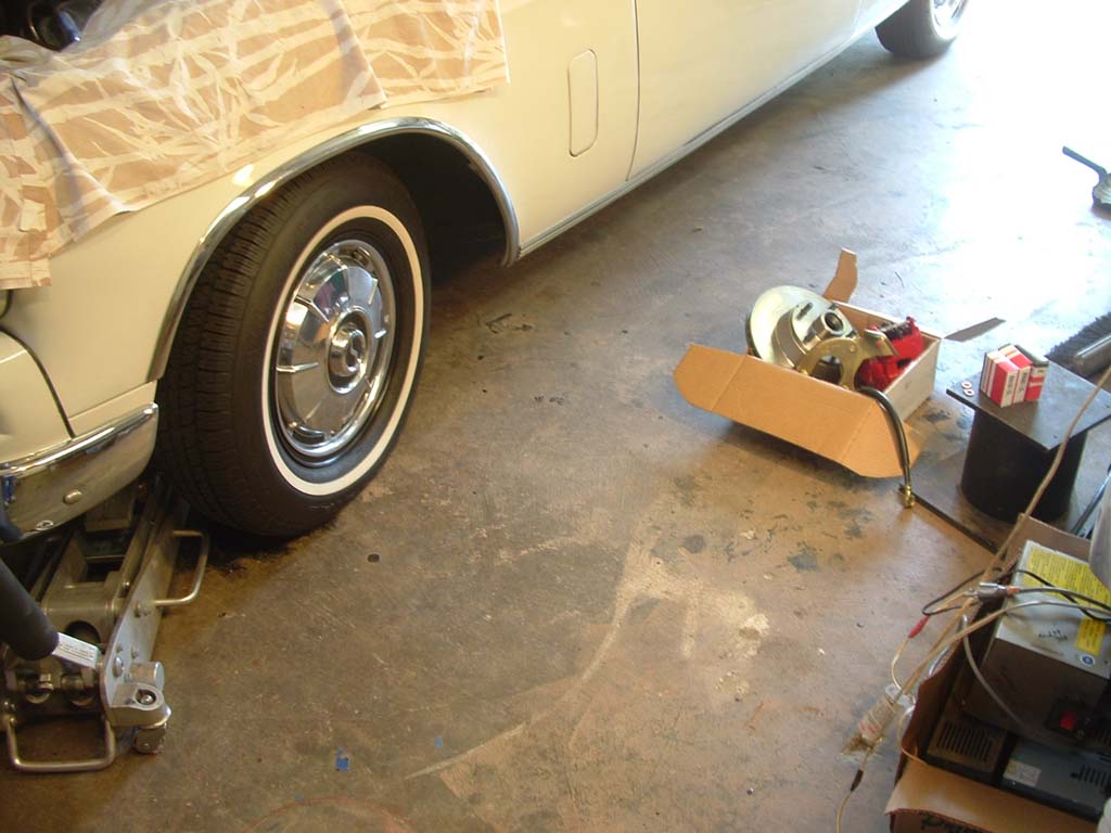 So, we start with my 64 Hawk, on which I just rebuilt the Stude Disk brakes. My Hydrovac isn't the best, so the decision was to install the latest Turner Kit.. |
 Start by checking the shipment for parts, against the included instruction sheet. The drivers side uses the parts stamped "Left", both bracket and caliper |
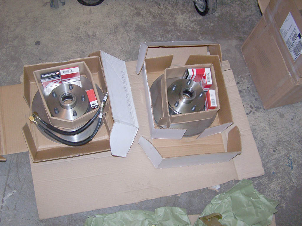 Rotors, bearings, seals and brake hoses, with copper sealing washers. All bolts are screwed into the brackets. Both inner and outer bearing races are installed in the rotors. You do have to supply the red Lok-tite.. |
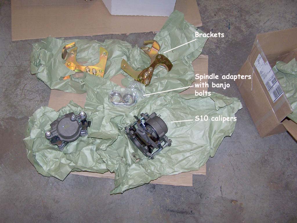 Brackets, spindle adapters, banjo bolts and loaded calipers. You need to supply the Red Lok-tite, brake fluid, (Disk brake)wheel bearing grease, a couple 1/8" washers for the spindle and 3-6 hours of your time. |
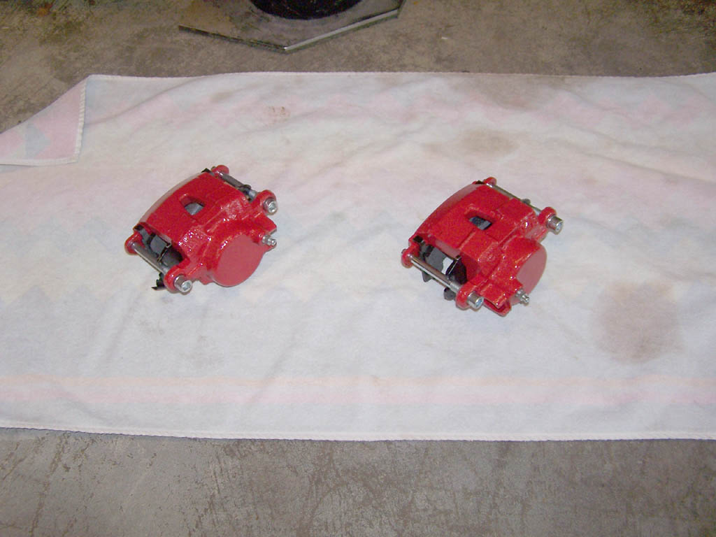 ..A little rustproofing, was in order.. |
|
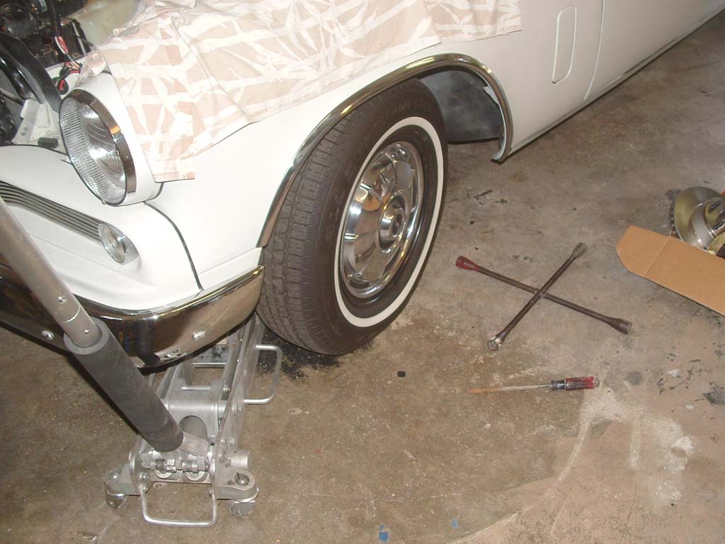 Here we go..... |
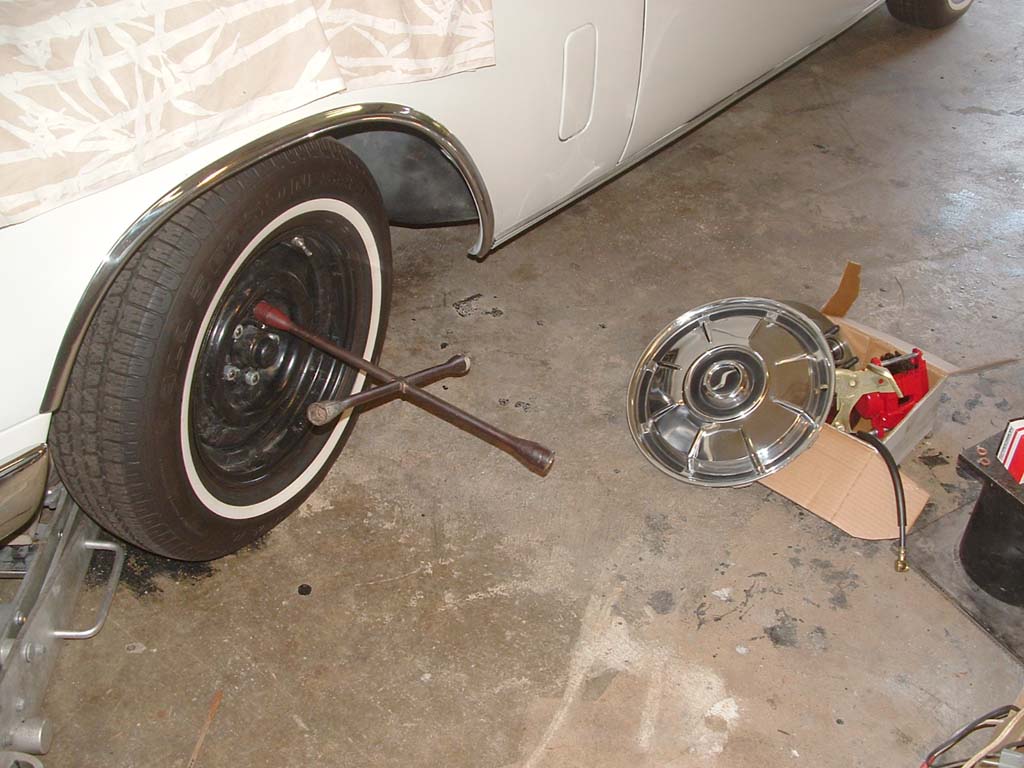 Pop the hubcap and crack loose the lug nuts.... |
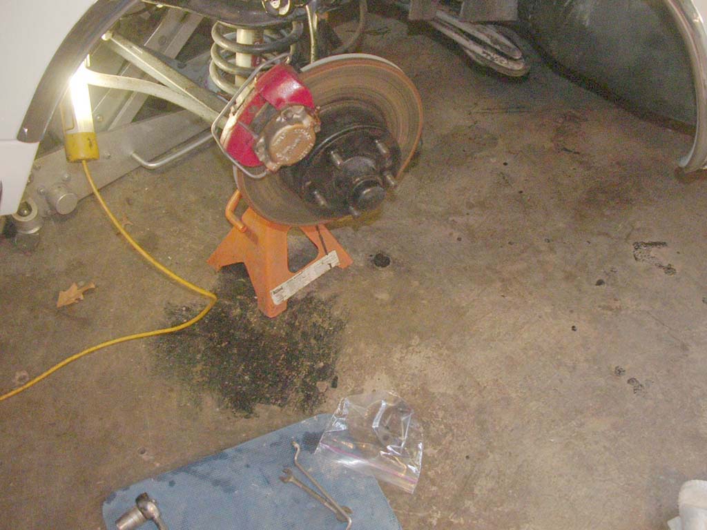
 Jack up at the center main and place jack stands where appropriate.. |
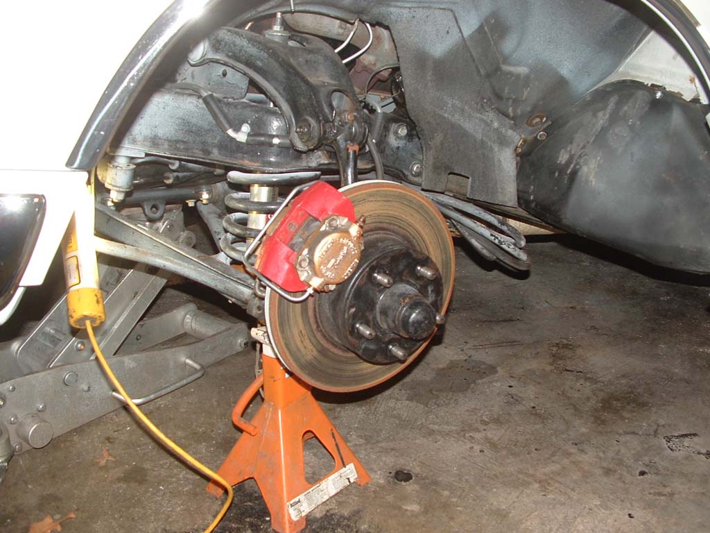
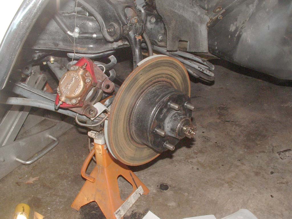
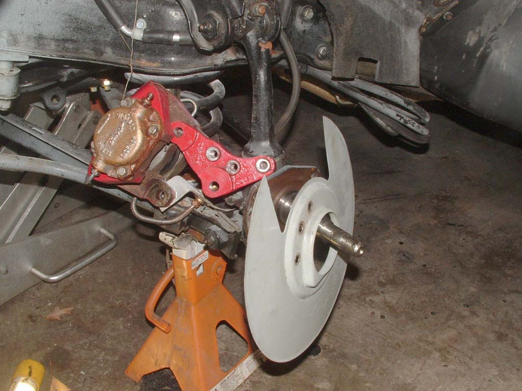
 Pull off the wheel and this is what your looking at.. |
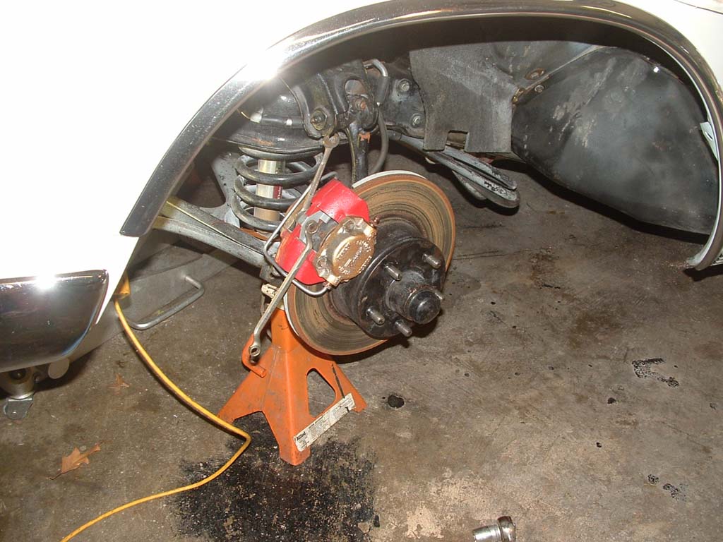 First up, is to remove the pad retainer. Two 7/16" wrenches are needed. |
 Put all your parts in separate plastic bags to keep things organized.. |
 Retainer is off.... |
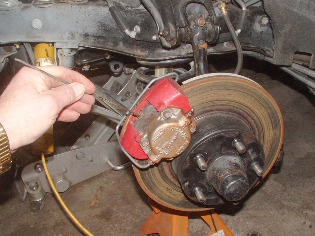 Use any kind of tool with a hook to pull the pads out of the caliper. If they're tight, smack the top side of the rotor with the palm of your hand to induce the wheel bearing play to loosen the pads.... |
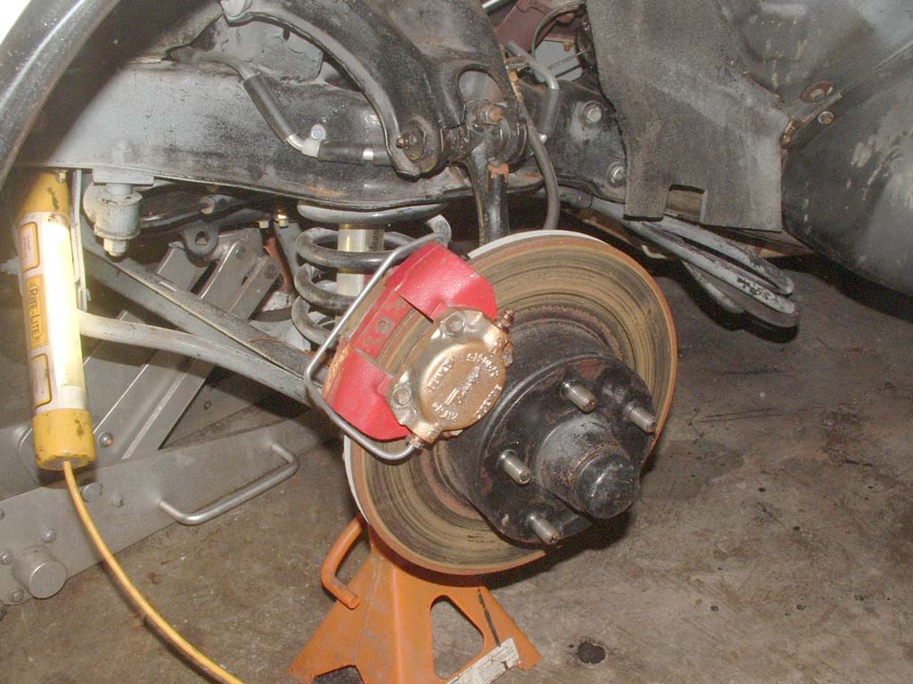 The rotor will turn freely without the pads.. |
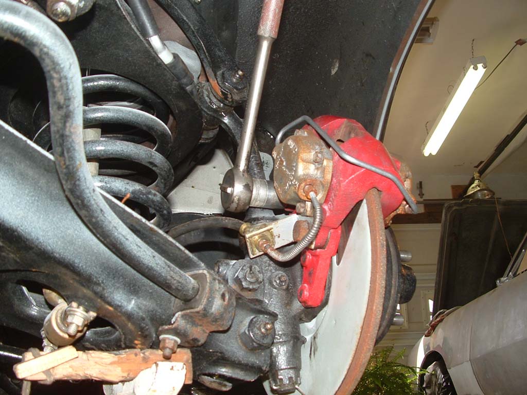 On the back side, use a 3/4" socket to break loose the two caliper retainer bolts. Remove the lower one and just back the top one off a few turns... |
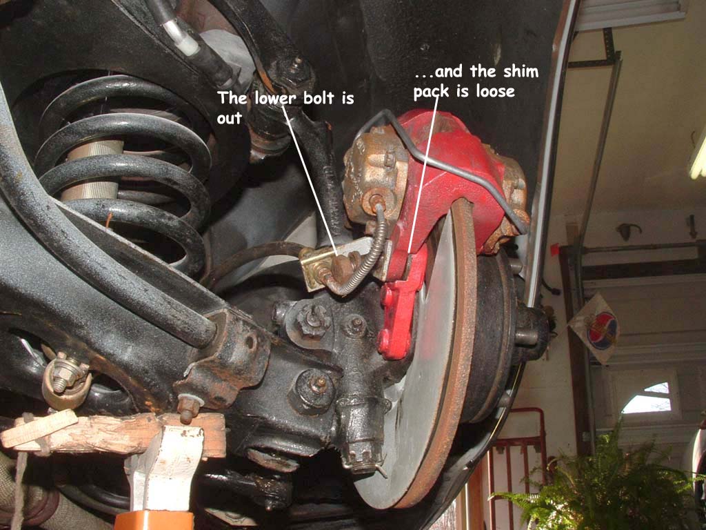 Enlarge this pic to see the shim pack |
 Swing the lower part of the caliper up, to expose the lower shim pack |
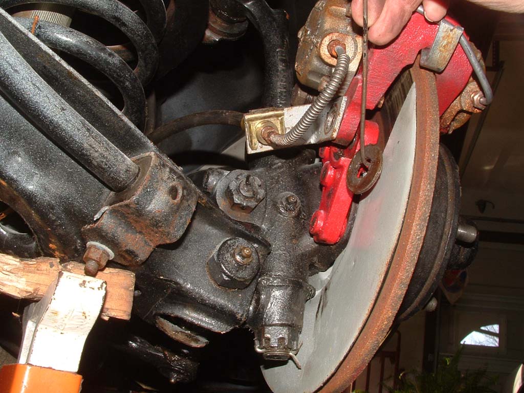 Remove the shim pack with your hook tool, wire together and set aside... Remove the upper bolt and take the shim pack out the same way. If you're just rebuilding your Stude calipers, then keep the shim pack marked and together for reassembly under the same caliper ear. This will alleviate the arduous task of having to adjust the caliper clearance. Place bolts, washers and shims in a plastic bag.. |
 Insert some mechanics wire through the caliper ear to support it and tie it to the upper control arm, out of the way. this is only to avoid having to get into the brake fluid right now.. |
 Remove the wheel bearing dust cover |
 Remove the cotter pin, nut, washer and outer wheel bearing.... |
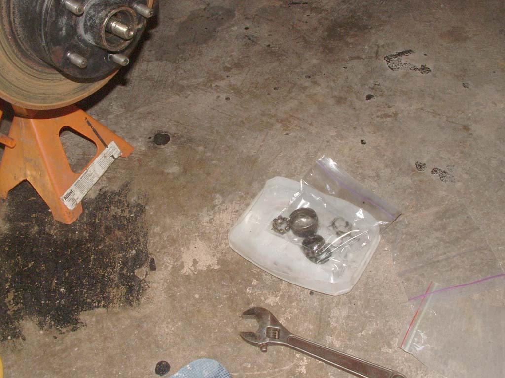 Put everything in a plastic bag... |
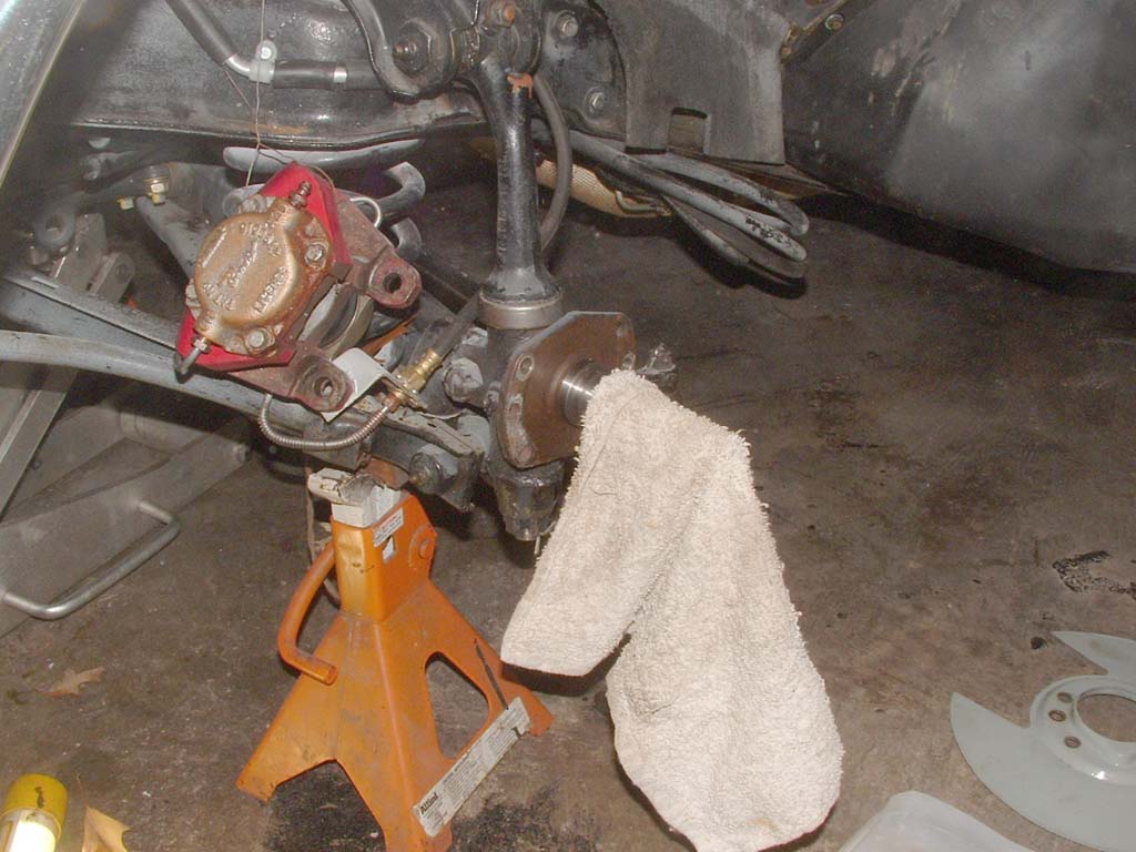
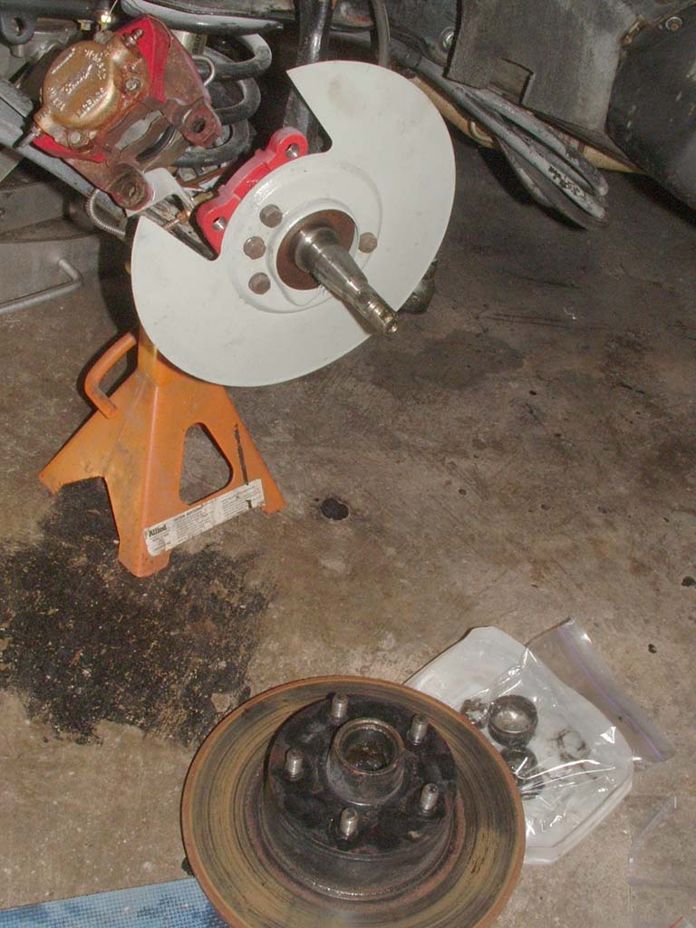 Grab the rotor firmly. It weighs about 20 lbs. Ease it off the spindle and be careful in setting it on the floor. |
 The next item are the rotor guards...( my favorite subject).. |
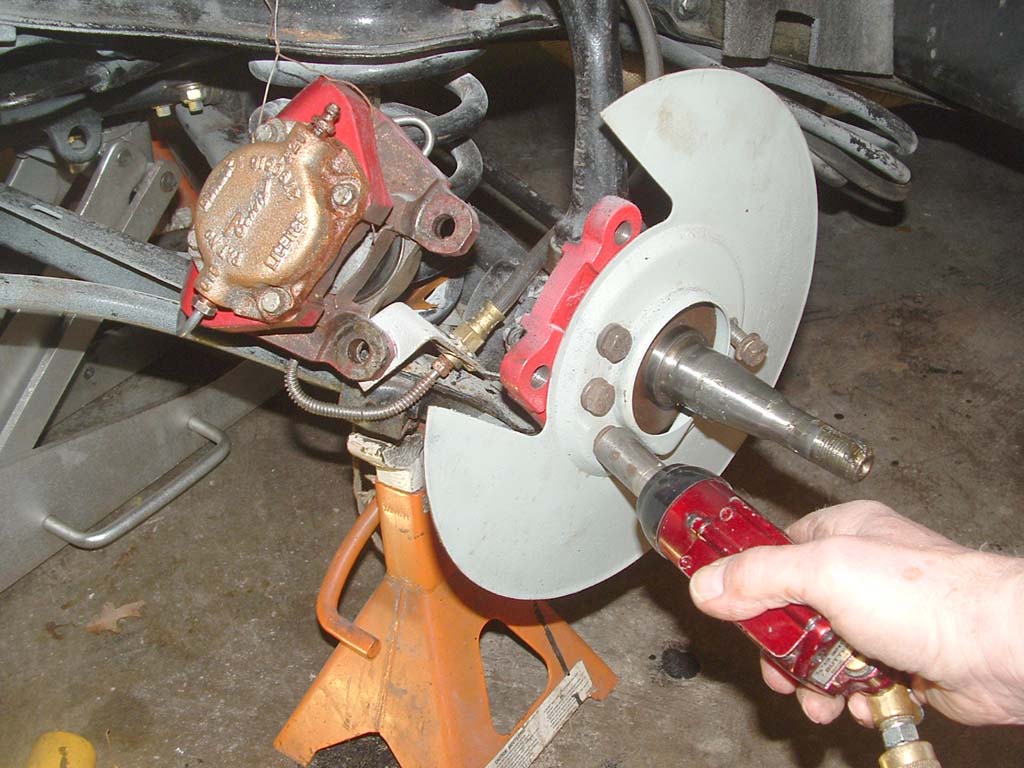 The bolts are 9/16". The three forward bolts thread into the spindle adapter. The lonesome one has a nut and washer on the rear... |
 Removing all the bolts will allow the stone guard and spindle adapter to be removed. At this point, you should go and repeat up to this step on the passenger side. |
 Clean up the spindle, in preparation for installation of the Turner kit spindle adapter... |
| PREPARATION BEFORE INSTALL... |
PREPARATION BEFORE INSTALL... |
BRACKET Preparation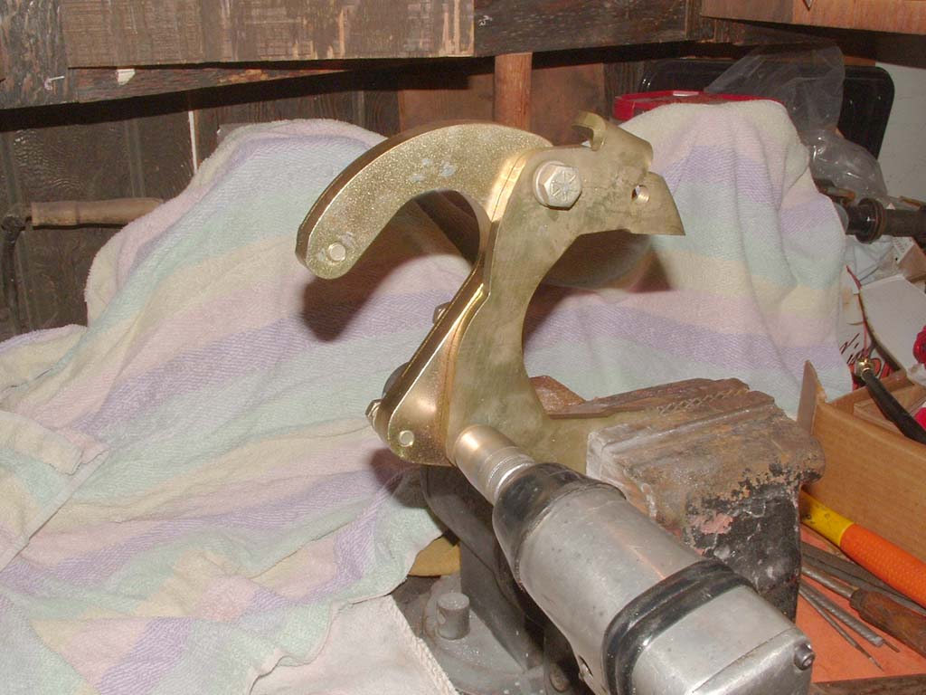 The brackets come loosely bolted, so first thing to do, is mount each bracket in a vise, with access to the two, large headed (3/4") bolts. |
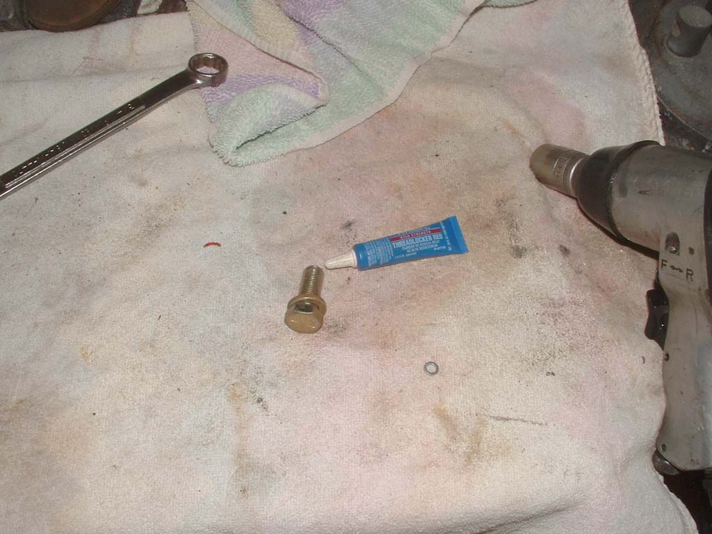 The brackets are heavy. So, ONE at a time, remove the LARGE 3/4" bolts. Treat the threads with red Lok-tite them and reattach them loosely. When both back on the bracket, fasten them. I torque the 3/4" bolts to 50 lbs. Leave the SMALLER (3/8") bolts alone for now. Only use RED lok-Tite on the threads of the bolts |
| DISK ROTOR PREPARATION 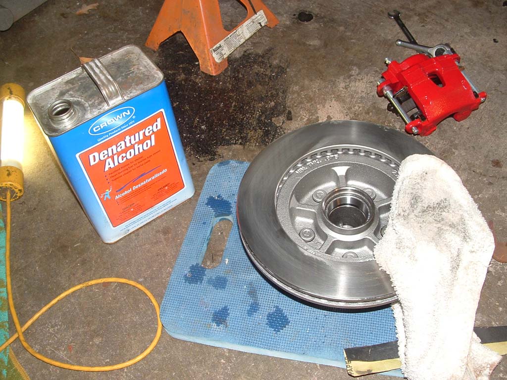 Clean the rotor with alcohol, especially inside the bearing cavity. Use a lint free rag, like a bedsheet. The bearing races are already installed, so the bearing itself, has to be packed with a good grade of "DISK BRAKE" wheel bearing grease. This a a high paraffin content grease and can withstand higher temps. |
 AFTER installing the inner bearing, TAP the seal in place with a wood block. |
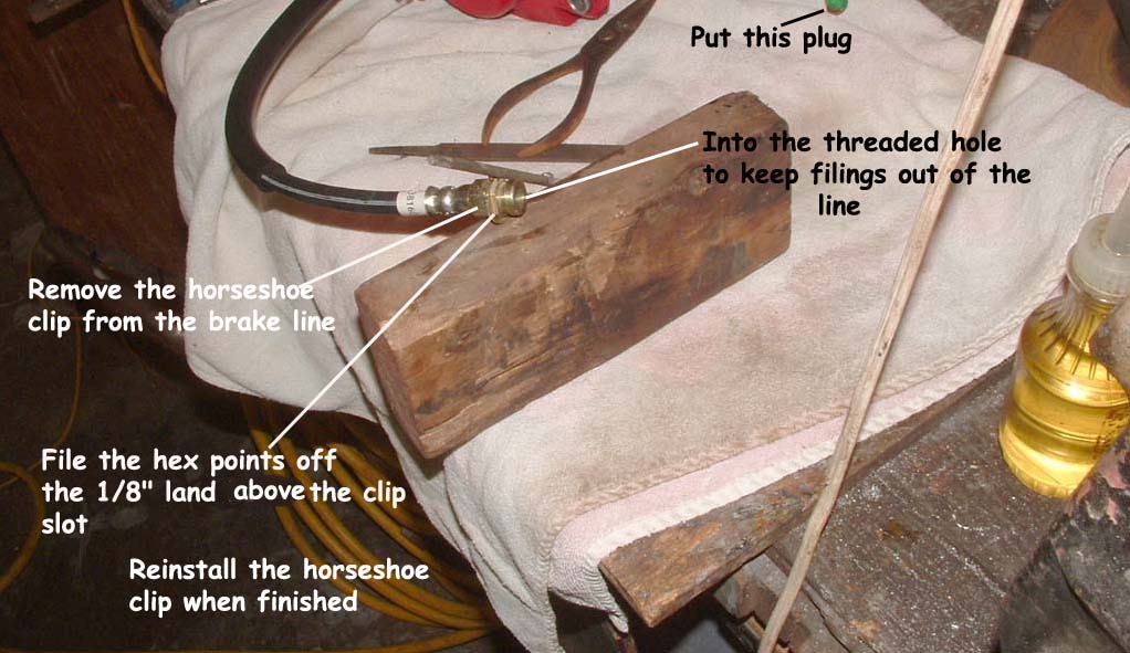
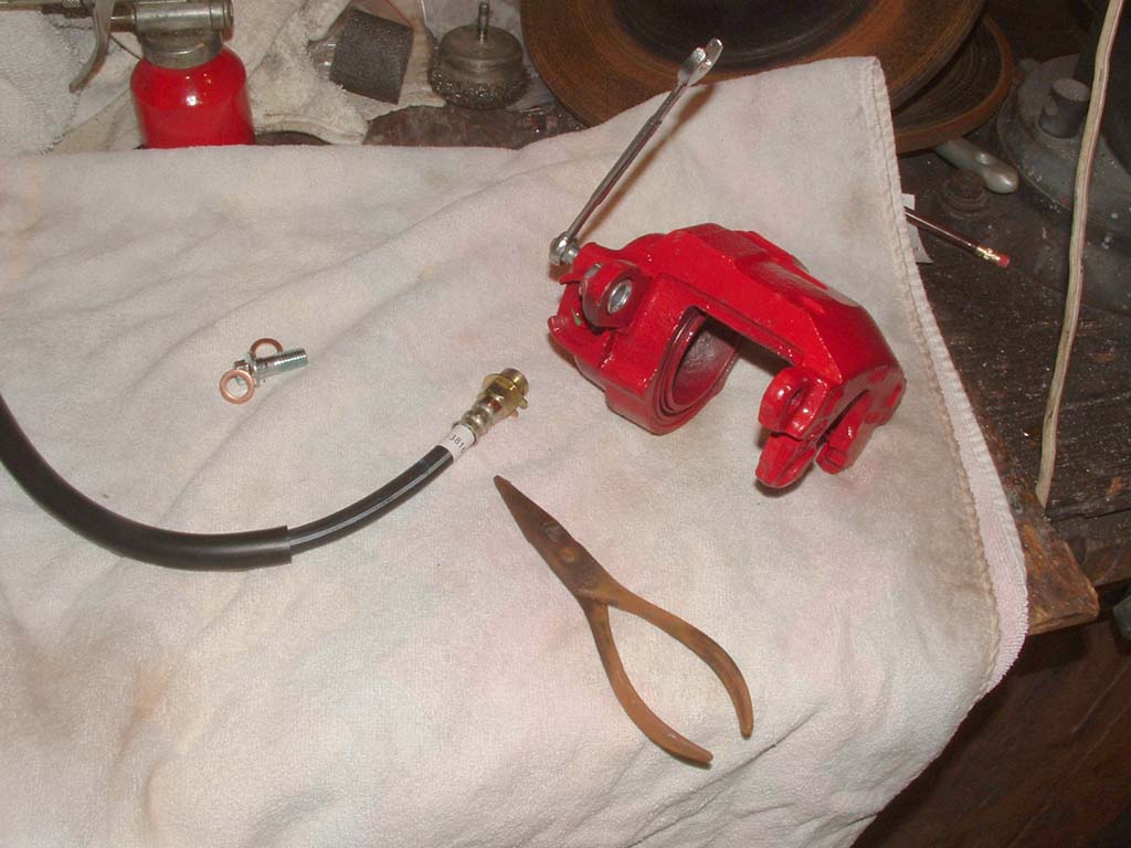
| BRAKE HOSE/CALIPER PREPARATION Any brake hose you buy these days to replace your worn Studebaker hose is a close fit to the original. The one part that almost doesn't fit, is the end of the hose that is attached to the steel brake line. The brake hose must fit thru a frame bracket, which is held fast by a horseshoe spring clip. The hole in the bracket is round, the end of the brake hose is hexagonal and the points of the hex prevent the shoulder from going thru the round hole in the bracket. So, you can't install the spring clip to hold everything in place. |
There's a loose C-clip on the brake hose end, which acts as a land, to allow the horshoe clip to firm up on the brass hose slot. this is easily removed as it is pretty maleable. By removing the C-Clip, you can mount the hose end in a vise and file the upper portion of the hex fitting round. |
 (click on me) |
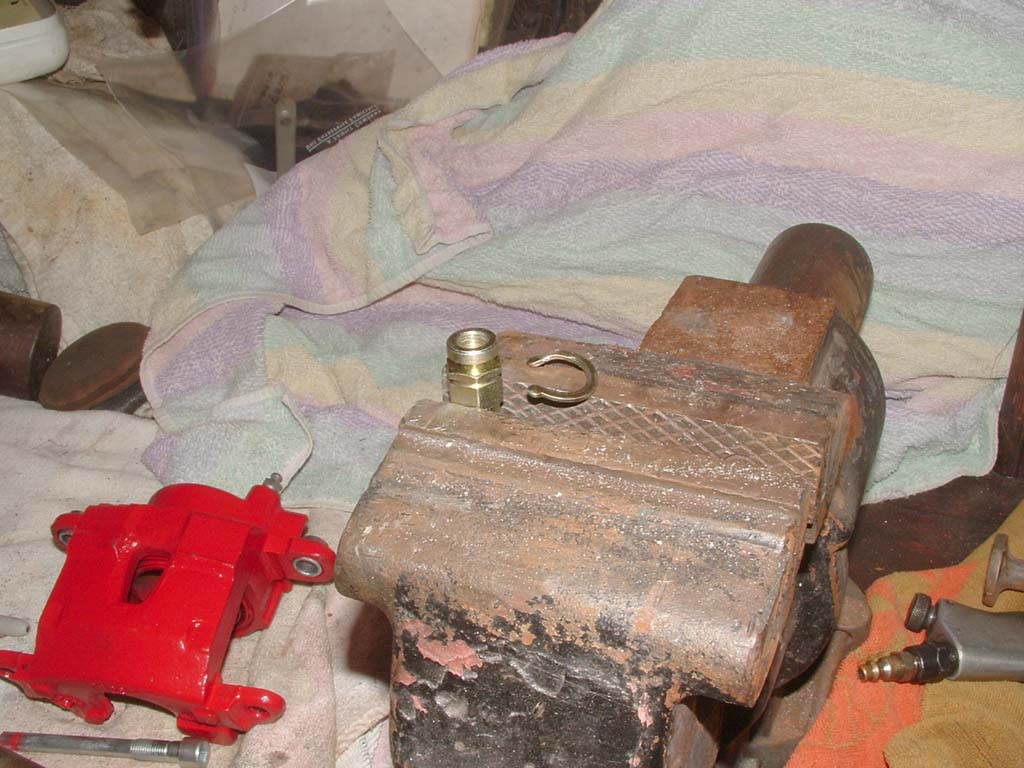 Remove the C-clip and mount the hose in the vise... |
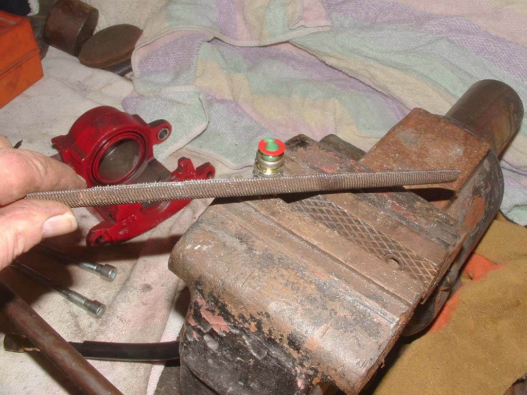 Place the brake line port plug from the caliper in the hose to prevent any filings from entering... |
 Now we move on to loading the caliper and final fit.
|
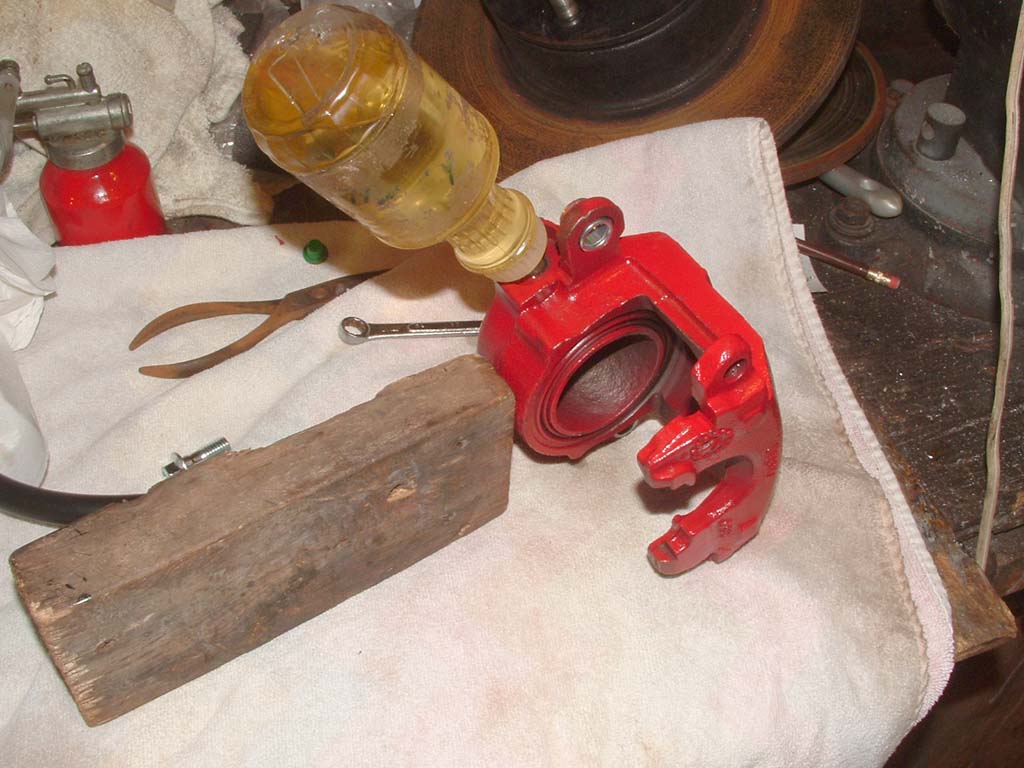 Loosen the bleeder screw (10mm)... Insert a squeeze bottle, containing your favorite brake fluid into the hose fitting orifice. Fill the caliper until the fluid comes out of the bleeder, without bubbles. |
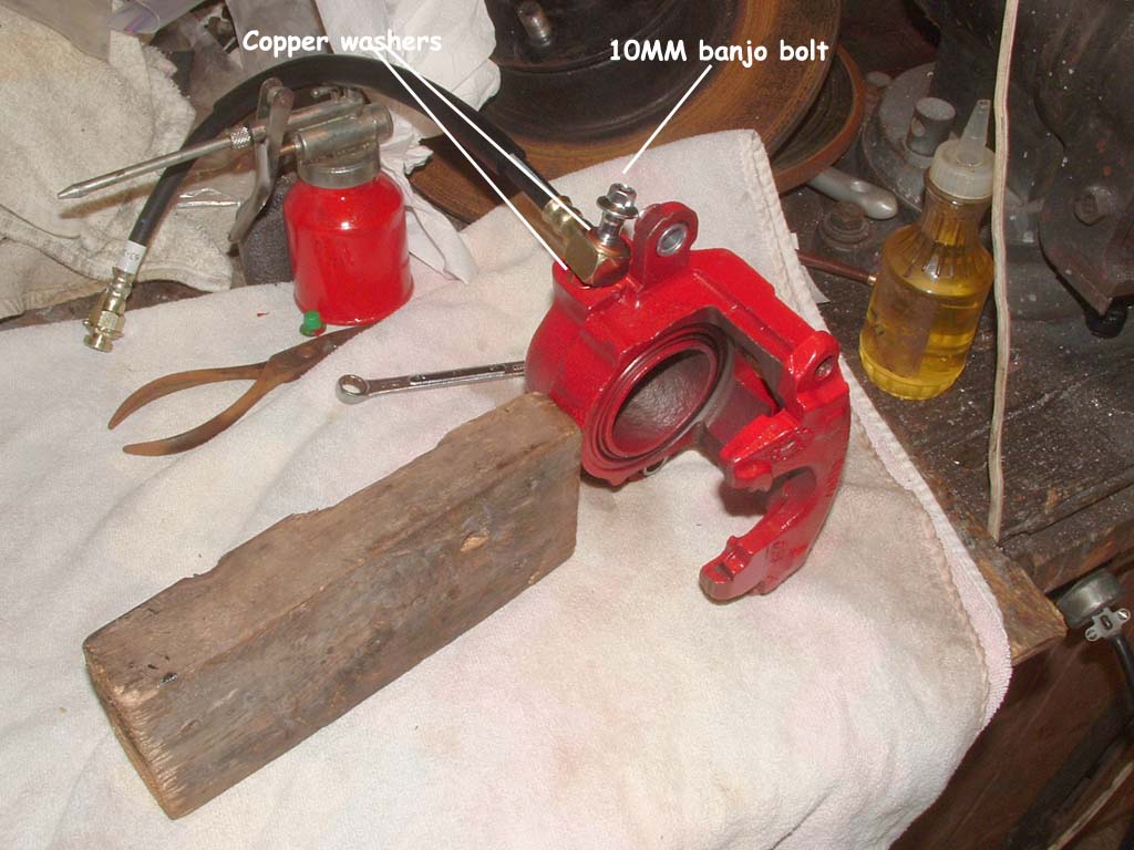 (Click on me) When the file work is done, attach the hose just lightly snug to the caliper. Be sure you use a copper washer on each side of the banjo fitting and the banjo bolt is also 10MM. Then, FILL the hose with fluid also.. |
 Test fit the Turner bracket to make sure you have the correct parts for the side you're working on..... |
|
| FITTING THE KIT |
FITTING THE KIT |
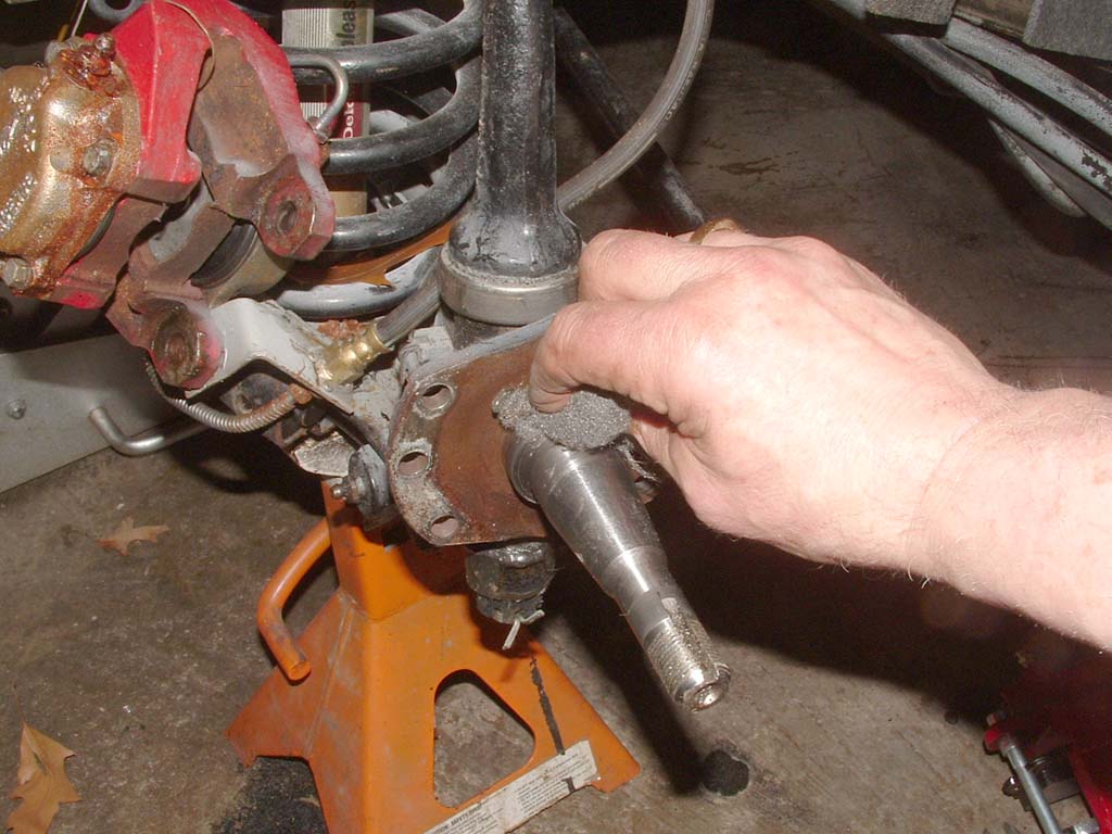 Clean up the spindle and shoulder with lacquer thinner or alcohol |
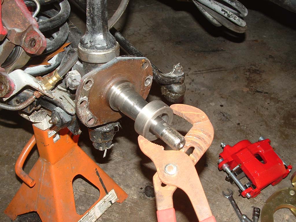 Go through the motions, beforehand, of carefully setting this piece on the spindle. After you heat it, you have to move surely and without hesitation. The outer circumference is where the seal rides, so don't grip the piece so tightly that it leaves score marks. Heat the piece with a propane, or quicker with Mapp gas, for about 2 minutes. It does NOT have to be cherry red, just very hot. You will see changes in the color as it heats up. |
 Immediately after placing the adapter, use an adequate size pipe to tap the adapter against the spindle. |
 It fits very snuggly over the spindle shoulder. |
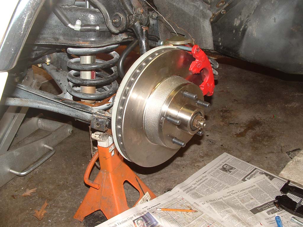
 Let the adapter COOL OFF and then test fit the rotor.....(notice the rotor guard?) 
|
 Test fit the caliper. It's installed WITH the pads in position. The inner pad has a locating spring, which fits in the piston, that can be difficult to keep in place.. The ears of the caliper fit behind the ears of the bracket... |
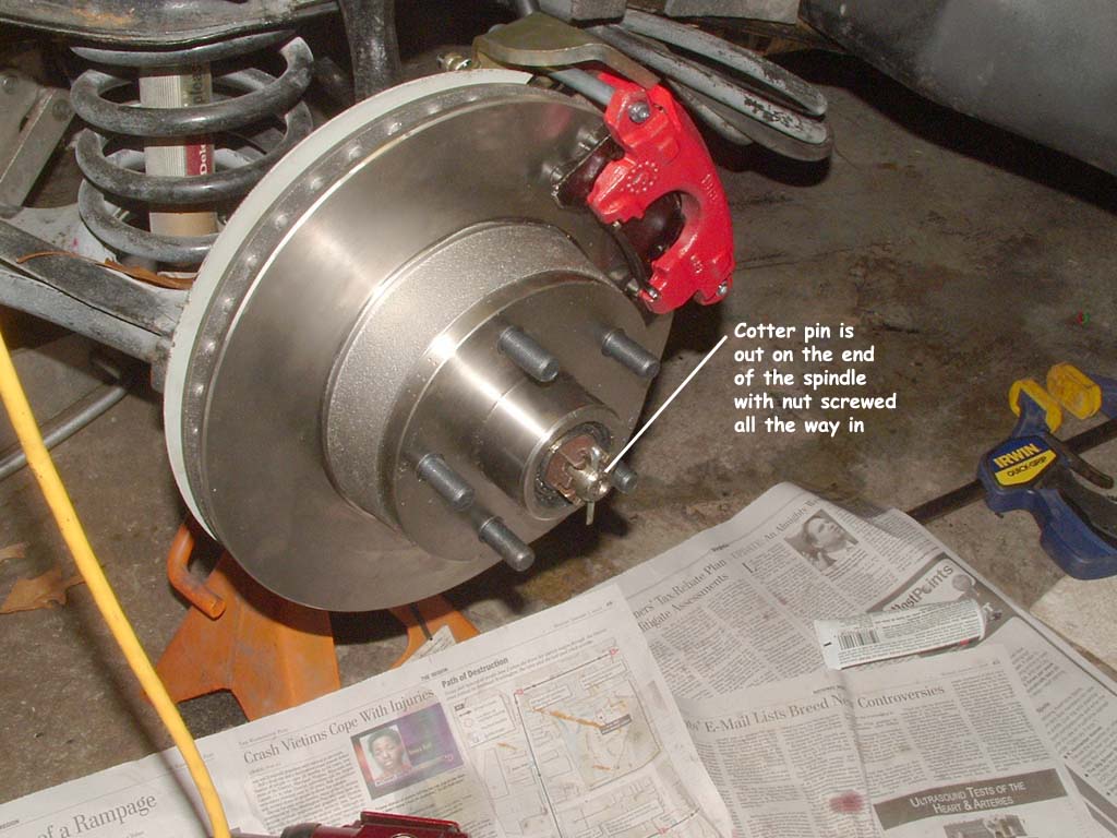 (click on me for more detail) Next item to overcome is the nut spacing on the spindle. The bearing depth in the new rotor causes the nut to thread on deeper onto the spindle, so the cotter pin is left out on the end and away from the nut. (See this pic) |
 The parts store some 1/8" washers to put behind the keyed spindle flat... |
| INSTALLATION OF THE CALIPER |
INSTALLATION OF THE CALIPER |
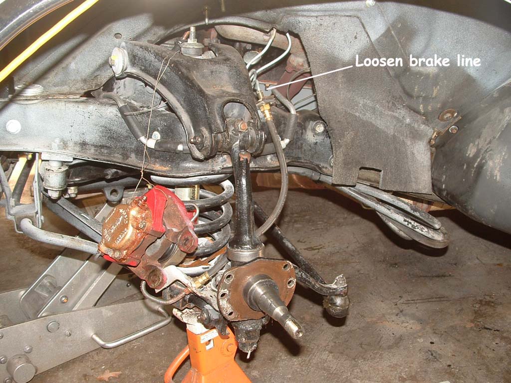 Go back to the Operation and loosen the brake line (3/8") from the brake hose (5/8".... |
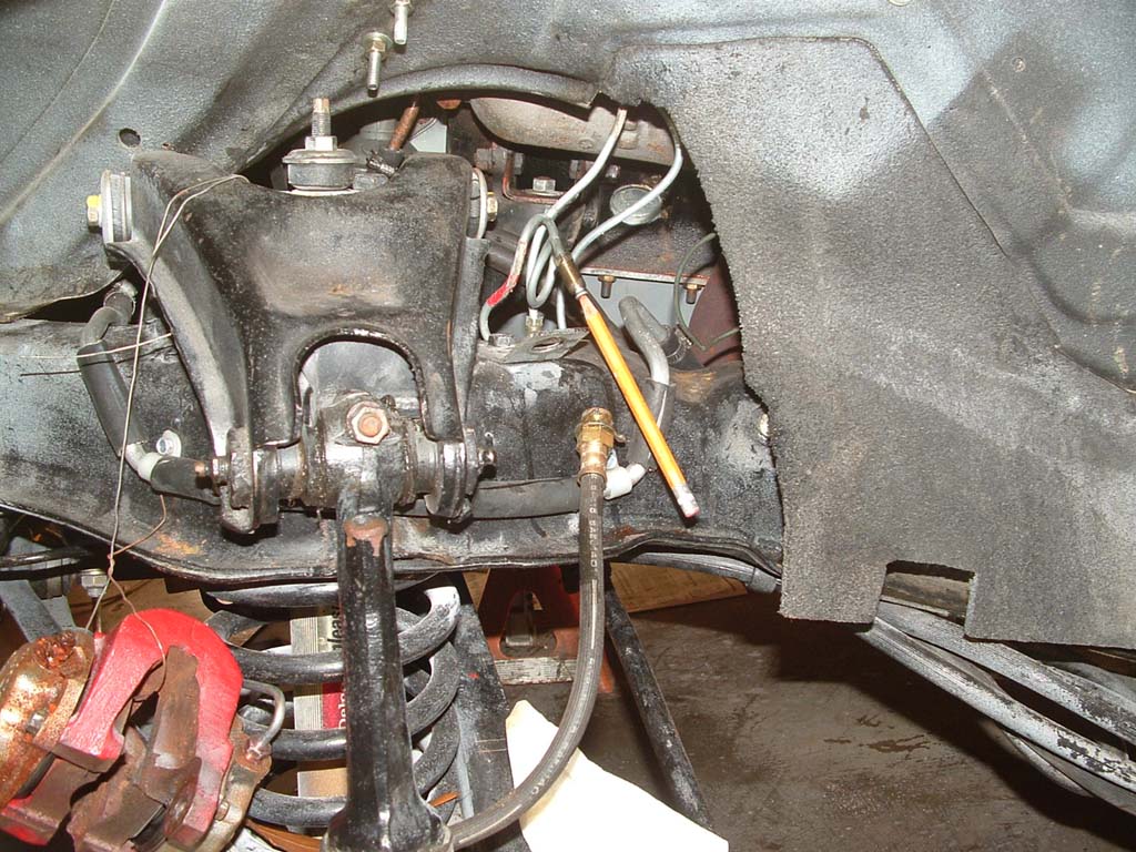 My 'M.O." is to put a pencil into the steel iine to stem the fluid from leaking all over. It fits very snugly and can be done quickly. Be sure there's NO point on the pencil. You don't want it breaking off and getting stuck in the line.. |
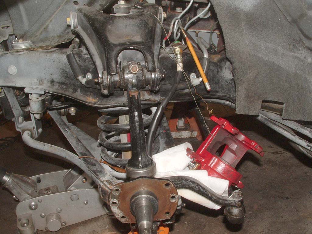 Remove the old caliper and wire the new S-10 caliper up on the right side. Align the hose up to the fitting and install the frame bracket, spring clip. The hose will easily mount in the frame bracket now that the hex points have been removed. Leave the hose disconnected from the brake line, right now.. |
 Install the bracket, and stone shields (If you're using them). Use RED LOK-TITE on the four 3/8" bolts. My spec is to tighten these is 35Ft/lbs. (The stone guards CAN be reused with this kit)
|
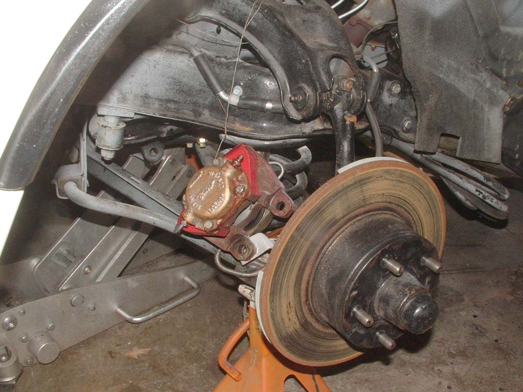
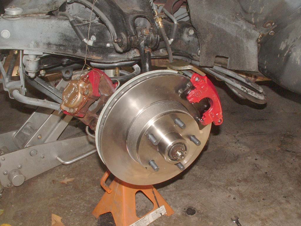
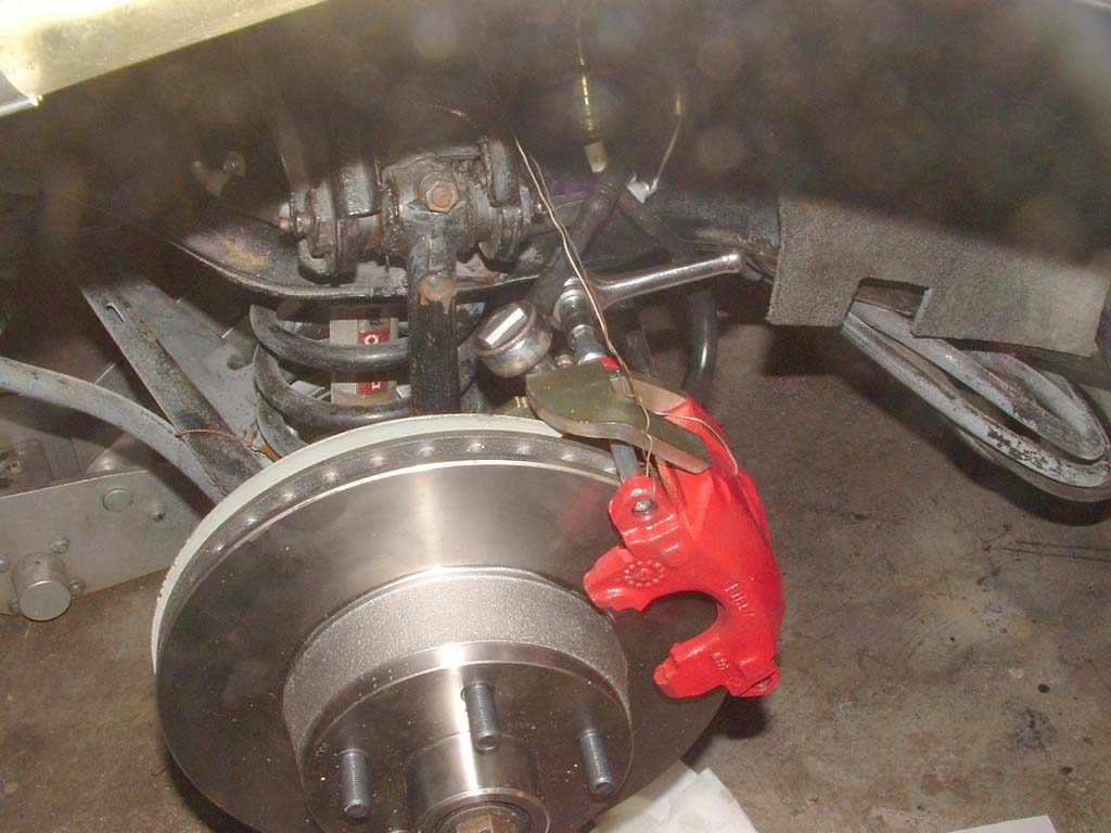
 Mount the rotor, caliper and pads. |
 The stone shields look pretty functional.
|
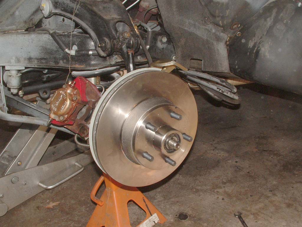
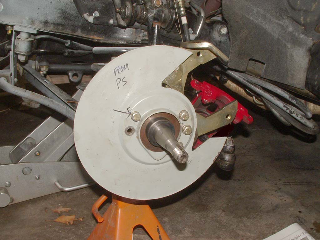
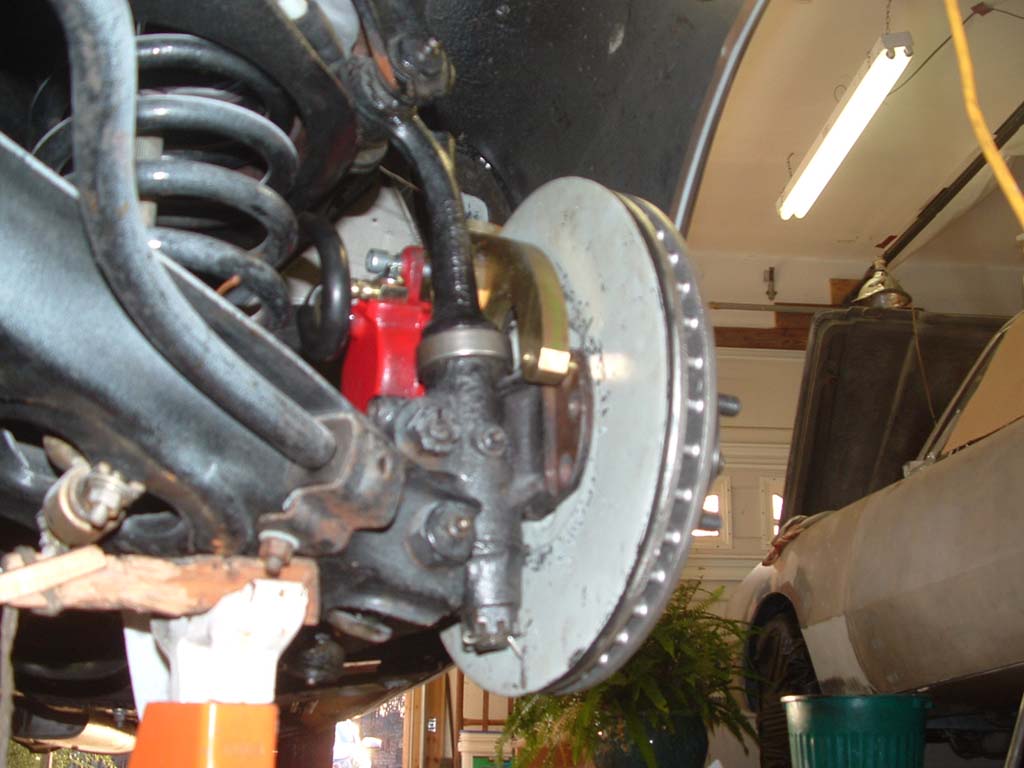
 Here's a pic of the passenger side without the stoneguards. Which would you rather have?
|
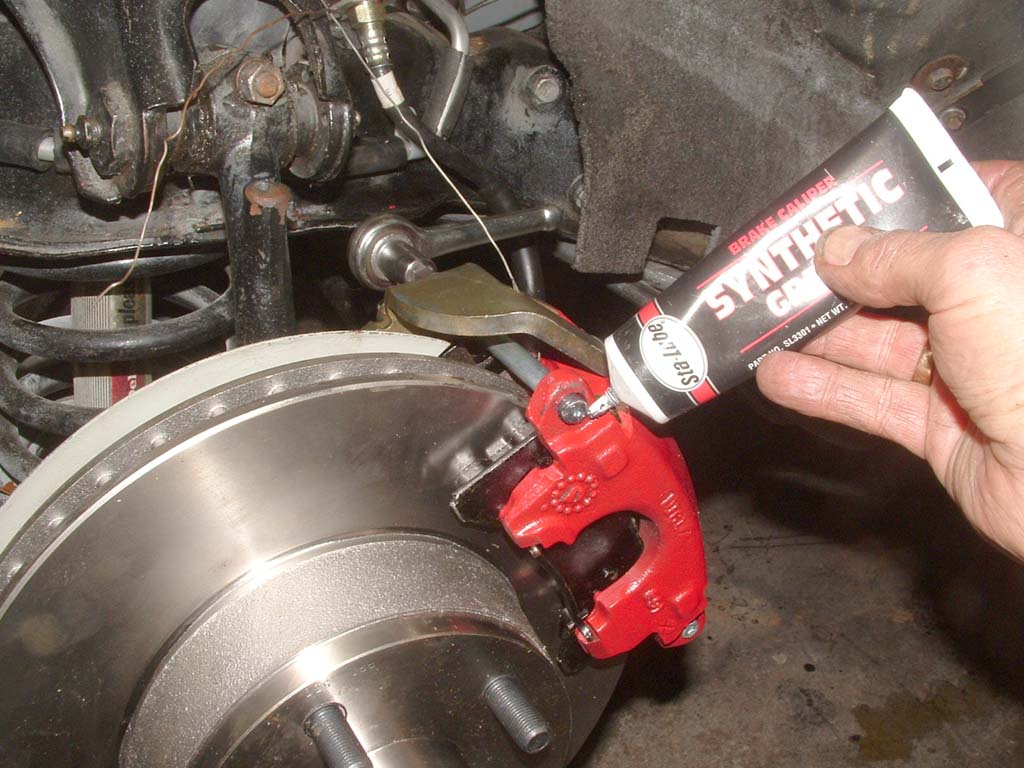 Use a small amount of silicone grease on the studs where they slide thru the caliper. |
 3/8" allen wrench on the caliper rods through the rear of the bracket. 10MM socket on the banjo bolt on the brake line. |
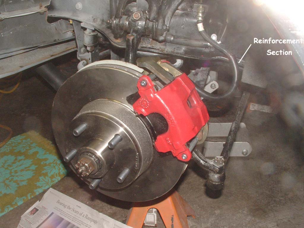 Once the banjo bolt is tight, let the brake hose twist in the frame clip until it relaxes into a rearward loop. Once the loop is evident, tighten the brake line. The mid secton of the brake line has an added buffer section to prevent chafing on the frame channel. Now you can bleed the lines and you're ......Done! |
![]()
Some technical opinions are my own from experience, other informational data is from online sources with credits when available and while care has been taken to be as accurate as possible, it is offered only as a guide and caution should be exercised in the application of it.